Wi-Fi Usage Instructions
English|Chinese
Introduction
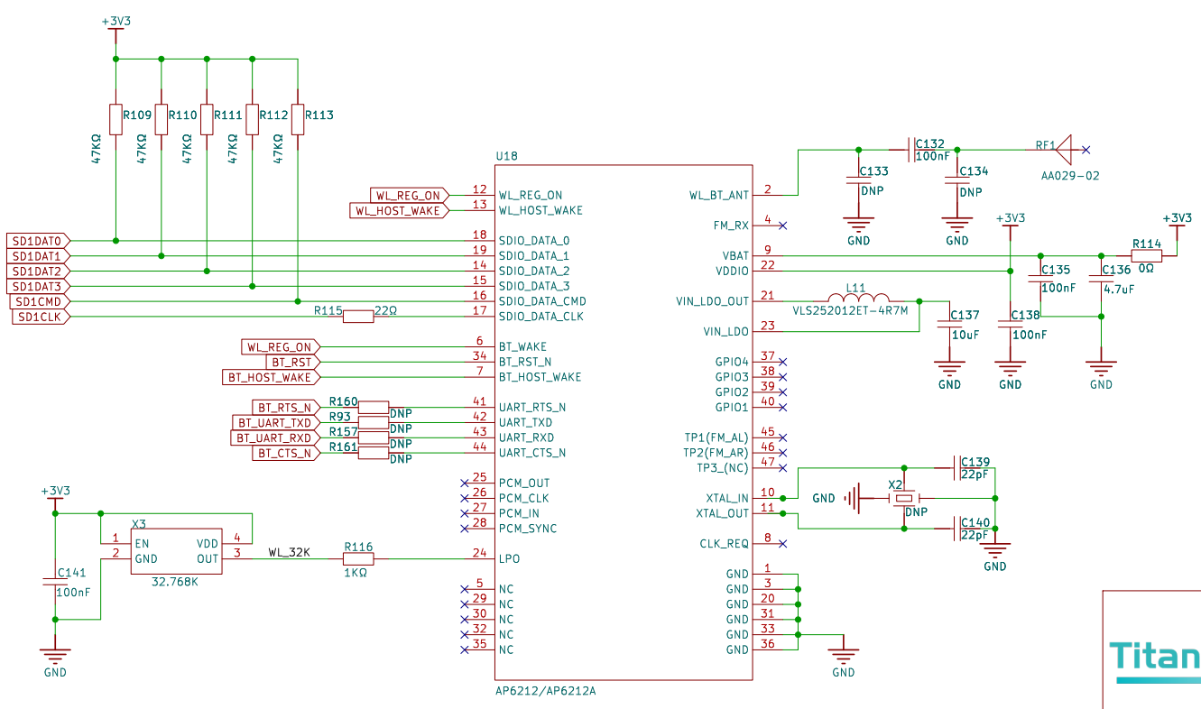
This example demonstrates how to use the RA8 series MCU SDHI module (r_sdhi) on the Titan Board to drive the CYWL6208-GS WiFi module, enabling wireless network connectivity via the SDIO interface. In this example, the MCU communicates with the CYWL6208-GS module (chip CYW43438) through the SDIO bus, and integrates with the RT-Thread network stack (lwIP) to achieve TCP/IP network functionality.
WiFi Introduction
1. Overview
WiFi (Wireless Fidelity) is a wireless local area network (WLAN) communication technology based on the IEEE 802.11 standard. It transmits data between terminal devices (such as MCUs, smartphones, PCs, or IoT devices) and access points (APs) via radio waves, providing short-range high-speed wireless communication.
WiFi is currently one of the most widely used wireless technologies, commonly applied in home networks, office networks, industrial control, smart homes, and IoT devices.
2. Working Principle
Communication Method
WiFi uses the ISM bands (2.4 GHz, 5 GHz, 6 GHz) and modulation schemes such as OFDM, DSSS, and QAM for data transmission.
WiFi networks consist of Access Points (APs) and Stations (STAs).
Data Transmission Flow
The STA scans for available WiFi networks.
STA sends authentication and association requests.
The AP completes handshake and key negotiation.
Once a secure communication channel is established between STA and AP, data transmission occurs.
3. WiFi Standards
Different WiFi versions correspond to the IEEE 802.11 standards:
Standard |
Frequency Band |
Max Rate |
Features |
|---|---|---|---|
802.11b |
2.4 GHz |
11 Mbps |
Early version, poor interference resistance |
802.11g |
2.4 GHz |
54 Mbps |
Backward compatible with 802.11b |
802.11n (WiFi 4) |
2.4/5 GHz |
600 Mbps |
MIMO technology |
802.11ac (WiFi 5) |
5 GHz |
3.5 Gbps |
MU-MIMO, 80/160 MHz channels |
802.11ax (WiFi 6) |
2.4/5/6 GHz |
9.6 Gbps |
OFDMA, lower latency, higher concurrency |
802.11be (WiFi 7) |
2.4/5/6 GHz |
>30 Gbps |
Multi-link operation (MLO), ultra-high throughput |
4. WiFi Modes
STA mode (Station): Device connects to an AP.
AP mode (Access Point): Device provides network access as a hotspot.
P2P mode (Peer-to-Peer/Ad-Hoc): Direct device-to-device communication.
Hybrid mode: Both STA and AP functions coexist.
5. WiFi Security
WEP (deprecated, insecure)
WPA/WPA2: TKIP/AES-based encryption, mainstream security
WPA3: Enhanced security, supports SAE handshake to prevent brute-force attacks
6. WiFi Characteristics
Advantages
High-speed transmission (Gbps level)
Widely supported (phones, PCs, MCUs, etc.)
Low cost, mature ecosystem
Can connect multiple devices simultaneously
Disadvantages
High power consumption, unsuitable for ultra-low-power applications
Limited transmission range (typically 10–100 m)
2.4 GHz band prone to interference (Bluetooth, microwave ovens, etc.)
RA8 Series SDHI Module Introduction
The RA8 series MCU SDHI (SD Host Interface) module is a host controller compliant with SD/SDIO/eMMC standards, capable of communicating with storage devices (SD card, eMMC) or SDIO peripherals (e.g., WiFi, Bluetooth modules) via 1-bit or 4-bit data lines.
In storage applications, it functions as an SD/eMMC controller for high-speed read/write operations. In peripheral expansion applications, it acts as an SDIO host to establish data channels with WiFi, Bluetooth, GNSS, and other modules.
In this example, SDHI is used to drive the CYWL6208-GS WiFi module (SDIO interface) to enable wireless networking for the MCU.
1. Key Features
SD Standard Support
SD v1.x / v2.x / SDHC / SDXC
Supports SPI mode and SD/MMC mode
High-Speed Data Transfer
Up to 50 MHz SDCLK (depending on MCU clock configuration)
Supports 1-bit / 4-bit bus
Automatic Command and Data Transfer
DMA support reduces CPU usage
Automatic command sequence generation (CMD0~CMD63)
Error Detection
CRC7 for commands, CRC16 for data
Timeout detection and response error recognition
Interrupt Support
Card insertion/removal detection
Command completion
Data transfer completion
Error interrupt
2. SDHI Module Architecture
The RA8 SDHI module consists of the following sub-modules:
Command Control Unit
Sends commands (CMD0~CMD63)
Handles responses (R1, R2, R3, R7, etc.)
Supports command timeout detection and CRC check
Data Transfer Unit
Data send/receive via internal FIFO or DMA
Supports block read/write, maximum 512-byte block
Single/multi-block transfer modes
Clock and Bus Control
SDCLK generation and division
1-bit / 4-bit bus width switching
Configurable high/low-level hold time
Card Detection and Power Control
Detect card insertion/removal
Control card power if supported
Interrupt and Event Control Unit
Command completion interrupt
Data transfer completion interrupt
Error interrupt
Card insertion/removal interrupt
3. Workflow (Example: SDIO WiFi)
Hardware Initialization
Configure SDHI pins: CMD, CLK, DAT0~3
Enable clock, reset SDHI controller
Bus Initialization
Set clock frequency (initial low → high speed)
Send initialization commands (CMD0, CMD5, CMD3, etc.)
Enumerate device and assign RCA
Function Configuration
Identify SDIO WiFi device
Configure block size, bus width, transfer rate
Enable interrupts
Normal Operation
WiFi driver accesses control registers and data transfer interface
MCU exchanges large packets with WiFi chip via DMA + interrupts
Upper layer protocol stack (lwIP) completes TCP/IP communication
Hardware Description
FSP Configuration
The first step is to configure Flash. See the README.md in the
Titan_component_flash_fsproject for the Flash configuration.Next, configure SDHI1 and create a new
r_sdhistack:
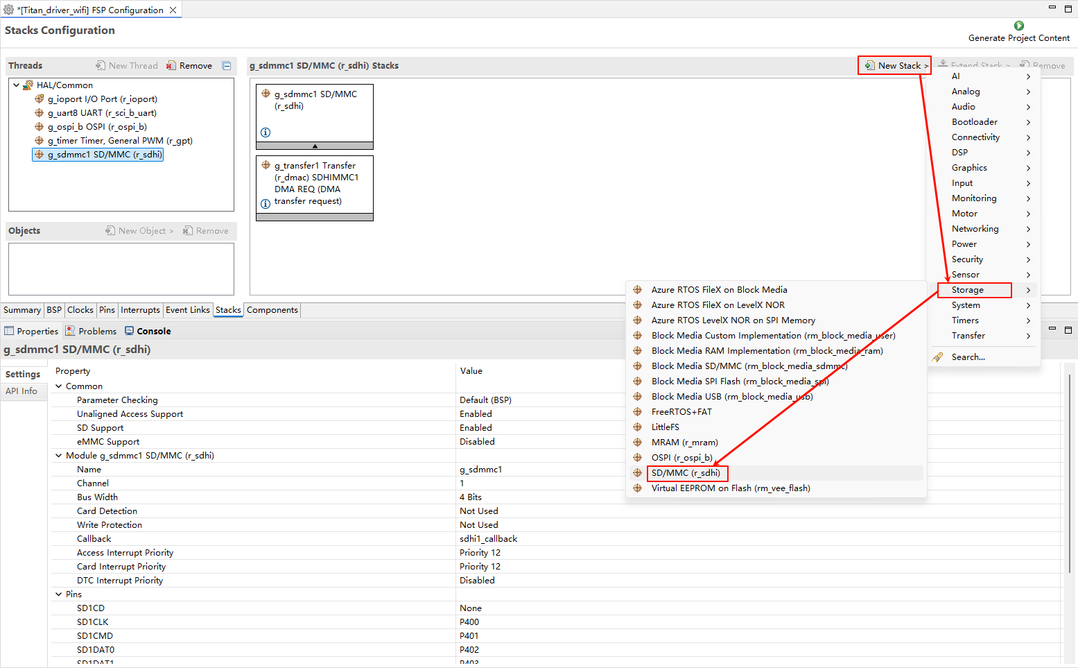
Configure
r_sdhistack:
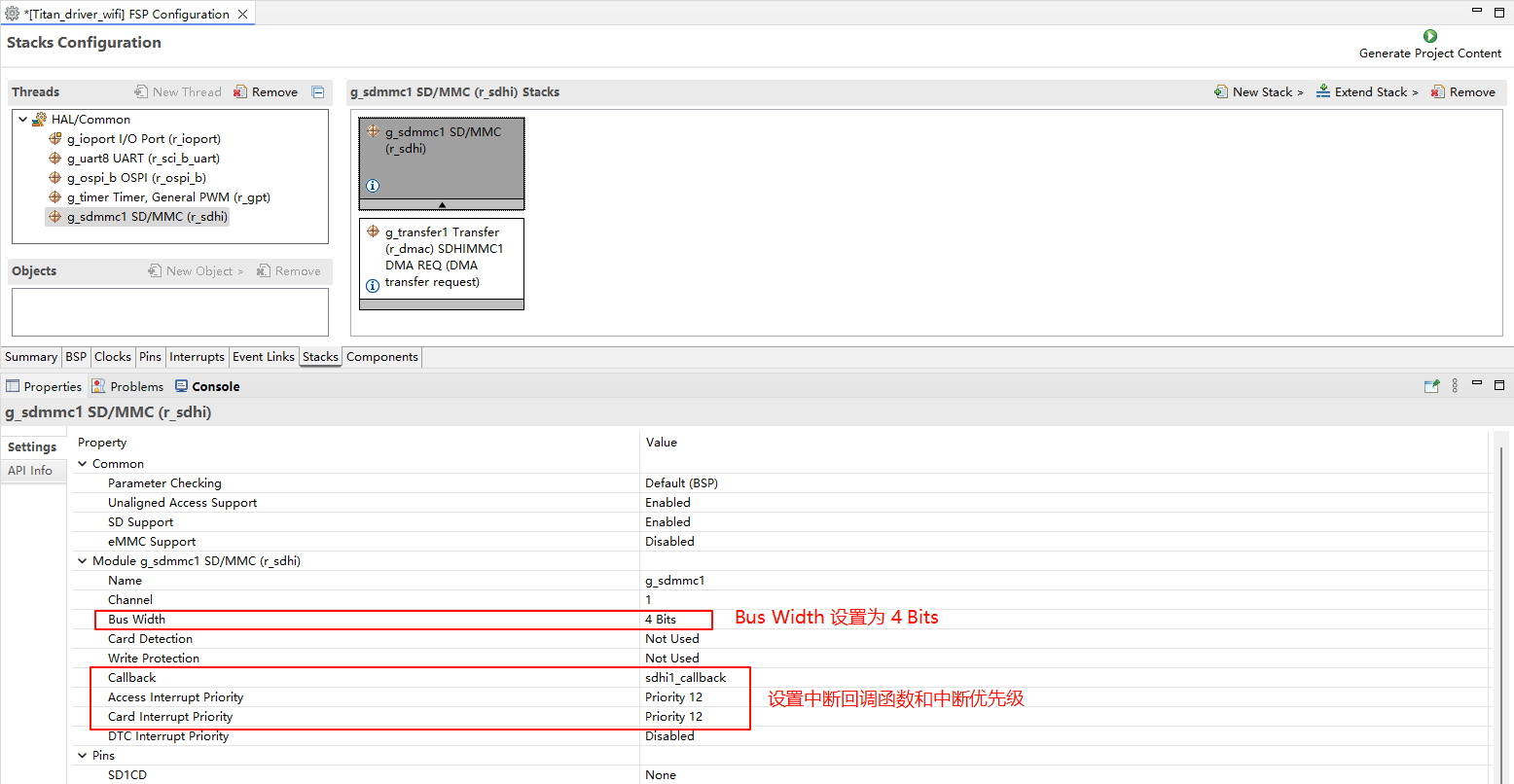
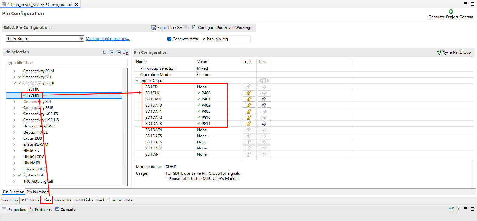
Configure SDHI1 pins:
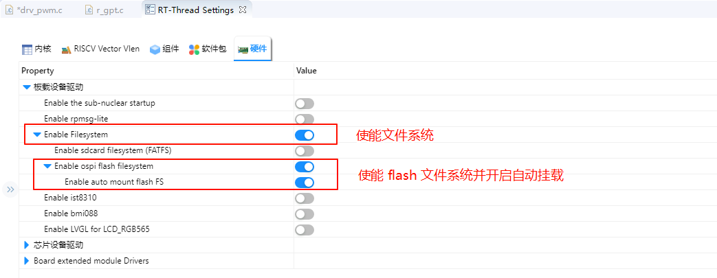
RT-Thread Settings Configuration
Enable ospi Flash.
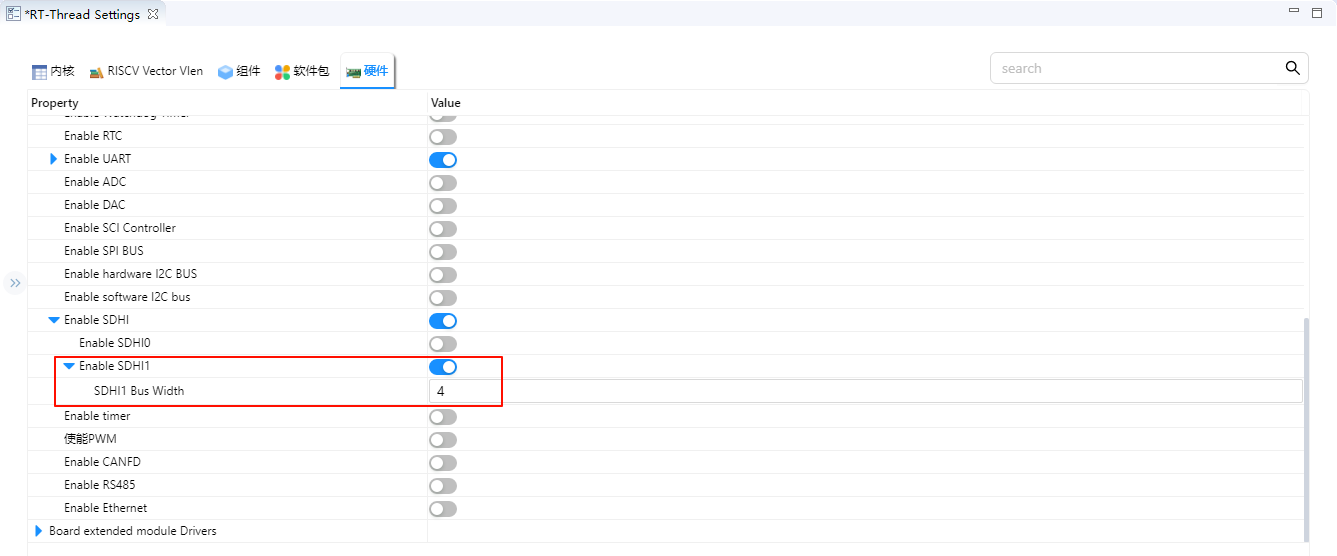
The Bus Width of SDHI1 is set to 4.
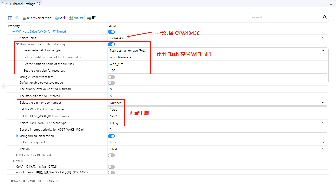
Configure the WHD package.
Compilation & Download
RT-Thread Studio: In RT-Thread Studio’s package manager, download the Titan Board resource package, create a new project, and compile it.
After compilation, connect the development board’s USB-DBG interface to the PC and download the firmware to the development board.
Run Effect
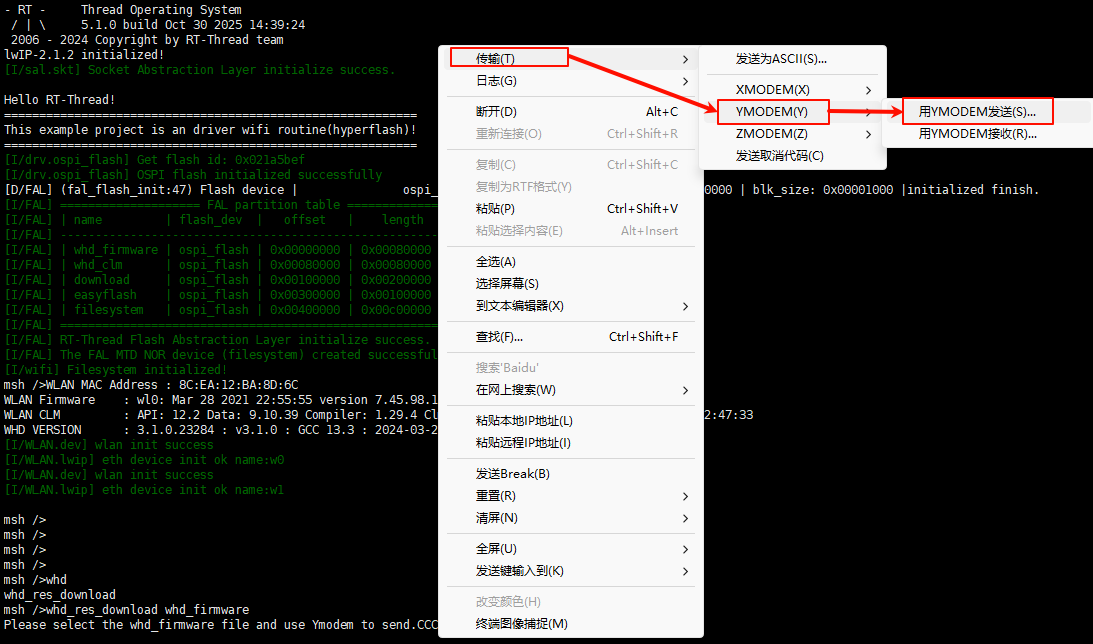
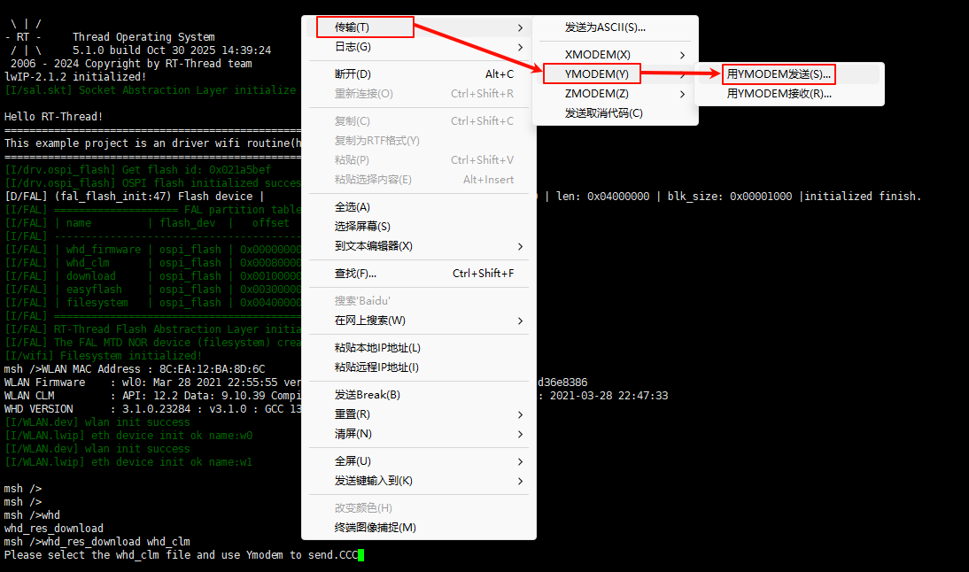
Press the reset button to restart the development board, if the terminal output firmware read error information, then you need to use ymodem to download WiFi firmware to Flash. Use the whd_res_download whd_firmware command to download 43438A1.bin into the whd_firmware partition of Flash; Use the whd_res_download whd_clm command to download 43438A1.clm_blob into the whd_clm partition of the Flash.
The WiFi firmware can be found in the /firmware folder of the project root.
Download WiFi firmware :
Use a serial tool that supports YMODEM, such as Xshell.
After entering the command whd_res_download whd_firmware, right-click in the window, then select Transfer → YMODEM → Send with YMODEM.
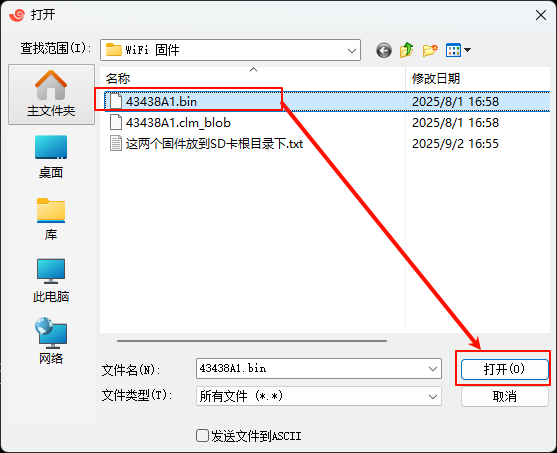
Select the 43438A1.bin file, then click Open to start flashing 43438A1.bin.
After entering the command whd_res_download whd_clm, right-click in the window, then select Transfer → YMODEM → Send with YMODEM.
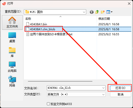
Select the 43438A1.clm_blob file, then click Open to start flashing 43438A1.clm_blob.
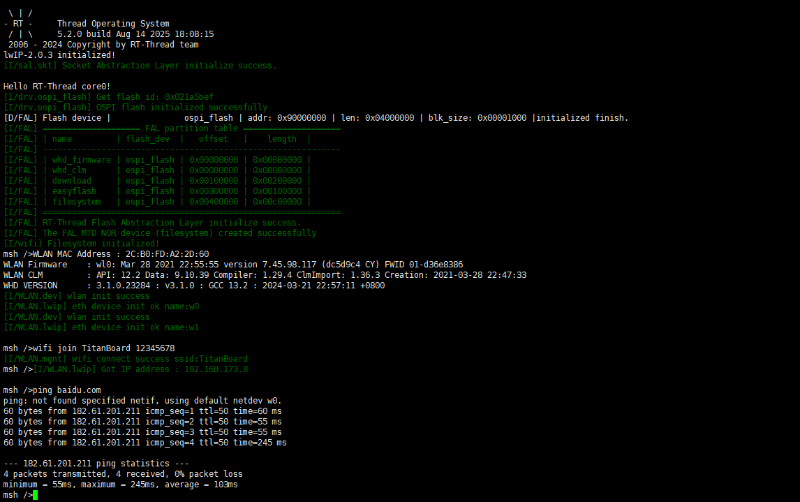
Test WiFi:
After downloading the WiFi firmware, reset the Titan Board, and you can see that the WiFi firmware is loaded normally and the WiFi module is initialized successfully. Then type wifi join ssid password to connect to WiFi and ping baidu.com to ping test.