IST8310 Example Usage Instructions
English | Chinese
Introduction
This example demonstrates how to use the I2C interface of the RA8 series MCU on the Titan Board to connect to the IST8310 three-axis magnetometer sensor and read data via the I2C driver framework provided by RT-Thread. Through this example, users can become familiar with the configuration of the RA8 I2C Master peripheral and the workflow for accessing sensors under RT-Thread.
IST8310 Magnetometer Introduction
1. Overview
The IST8310, produced by iSentek (Amys Semiconductor), is a three-axis geomagnetic sensor (Magnetometer) primarily used to measure geomagnetic field strength for electronic compass (E-Compass) applications.
It is commonly used in drones, smartphones, wearable devices, and navigation systems to provide heading information or detect magnetic fields.
2. Key Features
Three-axis measurement: Measures X, Y, and Z directions simultaneously
Communication interface: I²C (up to 400 kHz)
Measurement range: ±1600 µT
Resolution: 0.3 µT
Output rate: Configurable, up to 200 Hz
Low power consumption: Operating current ~85 µA, standby current <1 µA
Supply voltage: 1.8 V ~ 3.6 V (compatible with common MCUs)
Package: 3 × 3 × 1 mm LGA, compact for embedded applications
3. Working Principle
The IST8310 detects magnetic fields using the Hall effect or magneto-resistive effect, with the core process as follows:
Magnetic field detection
The sensing unit detects the geomagnetic field (~50 µT) or other magnetic variations.
Signal conditioning
Internal analog circuits convert the sensed signal into a voltage, then amplify and filter it.
A/D conversion
Built-in ADC converts the analog signal to digital values.
Data output
Outputs X, Y, Z magnetic field strength values via the I²C bus for the MCU to calculate heading or orientation.
4. Performance Specifications
Sensitivity: 0.3 µT / LSB
Offset error: Typical ±1 µT
Zero-point drift: Temperature compensation reduces drift
Sampling rate: Configurable from 0.5 Hz to 200 Hz
Operating temperature: -40 ℃ ~ +85 ℃
5. Advantages and Limitations
Advantages
Small size, low power consumption, suitable for battery-powered systems
Digital output, easy MCU integration
Wide operating voltage range, strong adaptability
Limitations
External calibration required (hard iron/soft iron correction) for accuracy
Sensitive to temperature and environmental magnetic interference
Alone, prone to noise; often fused with IMU (accelerometer + gyroscope)
RA8 Series I2C Master Features
The RA8 series MCU has a built-in I2C controller, a high-performance, multi-functional, master/slave-compatible module suitable for reliable, high-speed communication with I2C devices such as sensors, EEPROMs, and RTC chips.
1. Architecture Overview
The RA8 I2C controller consists of:
Master/Slave Control
Supports master, slave, and multi-master modes
Automatic bus arbitration and conflict handling
Supports 7-bit and 10-bit addressing
Clock Generator & Prescaler
Built-in programmable prescaler
Supports standard, fast, and high-speed modes
Allows precise baud rate configuration
Transmit/Receive FIFO
Independent TX and RX FIFOs
Reduces CPU intervention, increases data throughput
Supports batch read/write for high-speed sensor data acquisition
Interrupt Controller
Supports multiple events: transfer complete, arbitration lost, bus error, FIFO empty/full
Can be used in interrupt or polling mode
DMA Support
TX/RX data can be transferred via DMA
Reduces CPU load, lowers power consumption
Suitable for high-frequency or large-data I2C operations
2. Supported I2C Modes
Mode |
Speed |
Features |
|---|---|---|
Standard Mode |
100 kbps |
Compatible with standard I2C |
Fast Mode |
400 kbps |
Supports high-speed sensors and EEPROM |
Fast Mode Plus |
1 Mbps |
Increased bus bandwidth, reduced latency |
High-Speed Mode |
3.4 Mbps |
Suitable for high-speed data acquisition |
Address Mode |
7-bit / 10-bit |
Supports standard and extended slave addressing |
3. Bus Management & Multi-Master Features
Bus Arbitration
Detects conflicts automatically when multiple masters transmit
Follows I2C standard arbitration rules to avoid bus contention
Start/Stop Condition Generation
Hardware automatically generates START/STOP signals
Supports repeated start conditions
ACK/NACK Support
Automatically detects slave responses
NACK detection for communication error handling
Clock Stretching
Supports slave-held clock low for slow devices
Ensures reliable data transfer with slower slaves
4. Timing and Data Transfer
Bidirectional lines (SDA/SCL)
Open-drain, requires external pull-up resistors (4.7kΩ~10kΩ)
Supports 1.8V / 3.3V I/O
High-speed data transfer
Standard, fast, high-speed modes supported
Fast-Mode Plus up to 1 Mbps
Multi-master, bidirectional synchronous communication supported
FIFO & Burst support
8~32 byte FIFO for continuous read/write
Reduces CPU interrupt frequency
5. DMA and Interrupt Mechanisms
DMA Support
TX/RX FIFOs can be linked to DMA controller
Auto-triggered DMA transfer reduces CPU load
Ideal for high-frequency sensor data acquisition or continuous streams
Interrupt Types
Transfer complete (TX empty / RX full)
Arbitration lost (multi-master conflict)
Bus error (START/STOP/ACK/NACK errors)
FIFO threshold (high/low water mark)
6. Fault Detection & Tolerance
Arbitration lost detection for multi-master safety
Bus error detection for illegal conditions
Slave non-response handling with configurable retries
SCL timeout protection to prevent long bus hold
7. Electrical & Power Features
I/O voltage: Configurable 1.8V / 3.3V
Low power mode: Supports idle bus entry
SDA/SCL idle power consumption very low
Deep sleep wake-up: I2C peripheral can wake the MCU
RT-Thread I2C Framework Introduction
The RT-Thread I2C (Inter-Integrated Circuit) framework is a unified interface provided by the RT-Thread device driver layer for managing MCU I2C bus devices and communication with slave devices. This framework abstracts I2C bus hardware into a standard device interface, allowing applications to perform master-slave data transmission through a unified API and supporting cross-platform development.
1. Device Model
In RT-Thread, I2C buses are managed as device objects (subclass of struct rt_device, type RT_Device_Class_I2C). Slave devices communicate via the I2C device interface. Developers do not need to manipulate hardware registers directly; all data transfers can be done using standard device interfaces.
2. Operation Interfaces
Applications access I2C buses through RT-Thread’s I/O device interfaces. Key APIs include:
Find I2C bus device
rt_device_t rt_device_find(const char* name);
I2C data transfer
rt_size_t rt_i2c_transfer(struct rt_i2c_bus_device *bus,
                          struct rt_i2c_msg         msgs[],
                          rt_uint32_t               num);
I2C message structure:
struct rt_i2c_msg
{
    rt_uint16_t addr;    /* Slave address */
    rt_uint16_t flags;   /* Read/Write flags */
    rt_uint16_t len;     /* Data length in bytes */
    rt_uint8_t  *buf;    /* Data buffer pointer */
};
For simplicity, RT-Thread provides wrapper functions to read/write data to/from I2C slave devices:
Send data to I2C slave
rt_size_t rt_i2c_master_send(struct rt_i2c_bus_device *bus,
                             rt_uint16_t               addr,
                             rt_uint16_t               flags,
                             const rt_uint8_t         *buf,
                             rt_uint32_t               count);
Receive data from I2C slave
rt_size_t rt_i2c_master_recv(struct rt_i2c_bus_device *bus,
                             rt_uint16_t               addr,
                             rt_uint16_t               flags,
                             rt_uint8_t               *buf,
                             rt_uint32_t               count);
3. Framework Features
Unified Interface: All I2C bus hardware is exposed to the application through the same interface.
Cross-Platform Support: Applications can be ported across different MCU platforms without modifying I2C code.
Flexible Data Transfer: Supports single or multiple message transfers, including repeated start conditions.
Easy-to-Use Wrapper Functions:
rt_i2c_master_sendandrt_i2c_master_recvsimplify read/write operations.Supports Multiple Transfer Modes: Can handle standard I2C read/write and complex communication scenarios.
Reference: RT-Thread I2C Bus Device
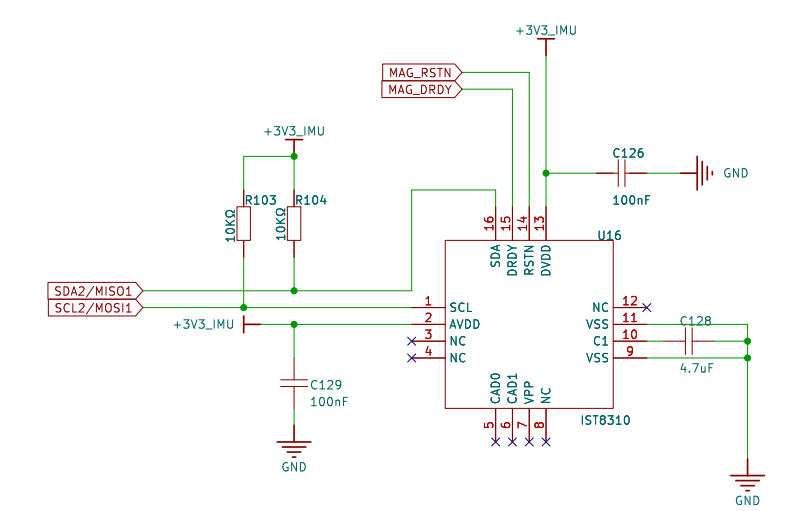
Hardware Description
Titan Board uses IIC2 to communicate with IST8310.
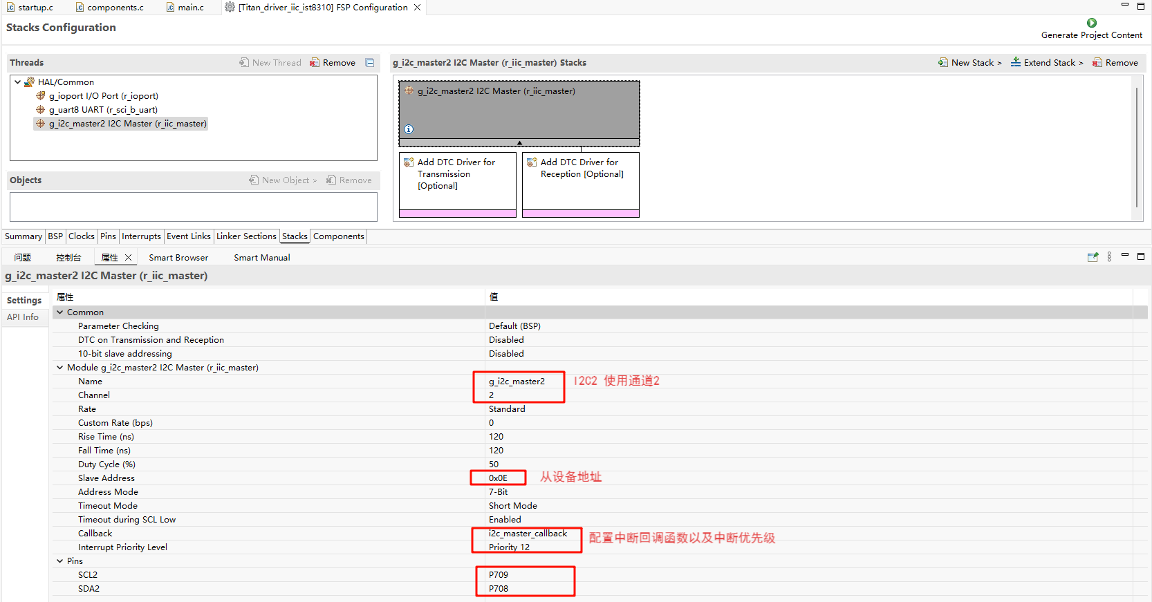
FSP Configuration
Create a new stack and select
r_iic_master. Then, configure the I2C2 settings as shown below:
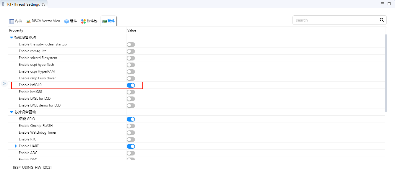
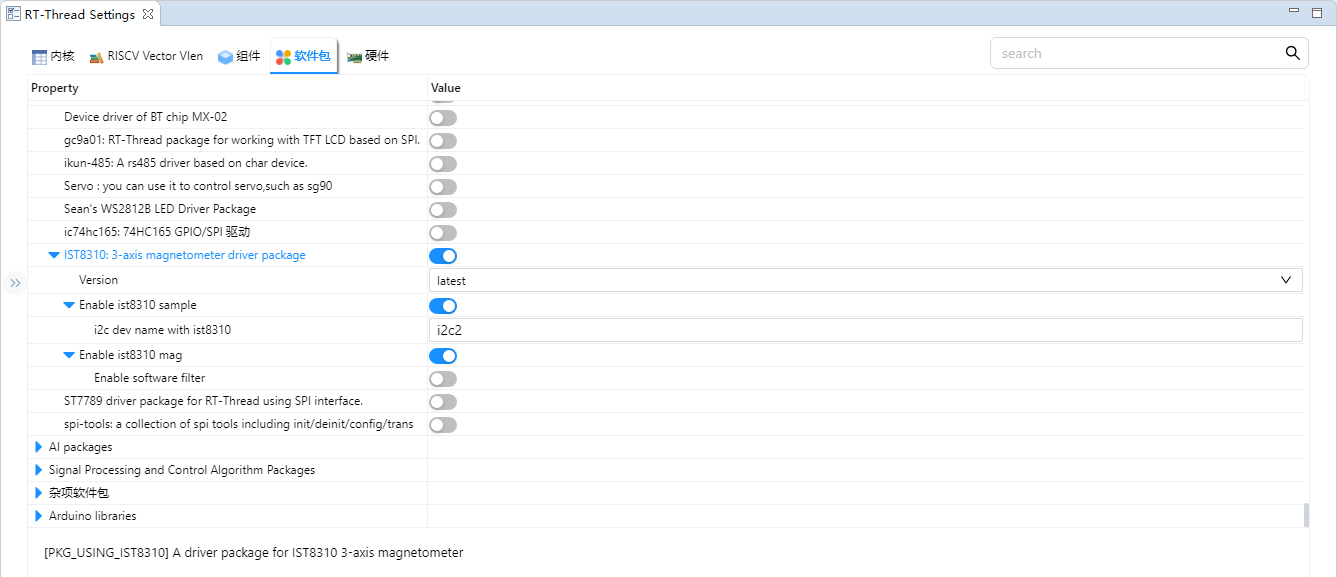
RT-Thread Settings Configuration
Enable the RT-Thread I2C driver framework and the IST8310 driver software package in the configuration.
Example Project Description
The magnetometer data communication is realized based on the driver software package IST8310.
/*
* Copyright (c) 2006-2025, RT-Thread Development Team
*
* SPDX-License-Identifier: Apache-2.0
*
* Change Logs:
* Date           Author        Notes
* 2025-06-13     kurisaW       first version
*/

#include <rtthread.h>
#include "ist8310.h"

static void ist8310_entry()
{
    ist8310_device_t dev = ist8310_init(IST8310_SAMPLE_I2C_DEV_NAME);
    if (dev == RT_NULL) {
        rt_kprintf("IST8310 init failed\n");
        return;
    }

    /* Set the magnetic declination Angle (set according to the actual position) */
    ist8310_set_declination(dev, 0.15f);  /* For example: 0.15 radians */

    while (1)
    {
        ist8310_data_t data;
        if (ist8310_read_magnetometer(dev, &data) == RT_EOK)
        {
            rt_kprintf("Magnetic: X=%.2f µT, Y=%.2f µT, Z=%.2f µT\n", data.x, data.y, data.z);
        }

        float heading = ist8310_read_heading(dev);
        rt_kprintf("Heading: %.2f°\n", heading);

        rt_thread_mdelay(1000);
    }
}

void ist8310_app()
{
    rt_thread_t ist8310 = rt_thread_create("ist8310", ist8310_entry, RT_NULL, 2048, 20, 10);
    if(ist8310 != RT_NULL)
    {
        rt_thread_startup(ist8310);
    }

    return;
}
MSH_CMD_EXPORT(ist8310_app, IST8310 app);
Compilation & Download
RT-Thread Studio: In RT-Thread Studio’s package manager, download the Titan Board resource package, create a new project, and compile it.
After compilation, connect the development board’s USB-DBG interface to the PC and download the firmware to the development board.
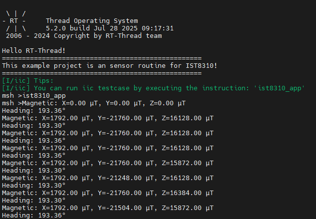
Run Effect
Input ist8310_app command in serial port terminal: