RS485 Driver Usage Instructions
English | Chinese
Introduction
This example demonstrates how to implement RS485 half-duplex communication on the Titan Board using the RA8 series MCU UART module, leveraging the RT-Thread serial driver framework for data transmission and reception. Through this example, users can become familiar with the configuration of RA8 UART peripherals, setting up RS485 communication modes, and application workflows under RT-Thread.
RS-485 Overview
1. General Description
RS-485 (also known as TIA/EIA-485) is a differential serial communication standard widely used in industrial control, building automation, and long-distance data transmission. It is an enhanced version of RS-232, supporting longer distances and multi-node communication.
Key features:
Differential signaling: Uses two lines (A/B) to transmit signals, improving noise immunity.
Multi-point communication: A single bus can support up to 32 drivers and 32 receivers (more with extended devices).
Long-distance transmission: Standard up to 1200 meters, with speed inversely related to distance.
Half-duplex or full-duplex: Flexible configuration; industrial protocols like Modbus RTU typically use half-duplex.
2. Physical Layer Characteristics
Feature |
Description |
|---|---|
Signal type |
Differential (A/B lines) |
Driver voltage |
±1.5 V to ±5 V |
Receiver threshold |
≥ ±200 mV |
Maximum nodes |
32 drivers + 32 receivers (standard) |
Bus length |
Up to 1200 m (longer at lower speeds) |
Termination resistor |
120 Ω, matches bus impedance, reduces reflections |
Differential signaling principle:
Lines A and B carry opposite currents.
The receiver measures V_AB = V_A - V_B.
Common-mode noise is rejected, maintaining correct logic levels.
3. Communication Modes
Half-Duplex
Single-direction communication on the bus.
Send/receive enable control switches direction.
Common in Modbus RTU and industrial protocols.
Full-Duplex
Uses two differential pairs (A/B + A’/B’) to transmit and receive simultaneously.
Increases communication efficiency.
Requires more complex PCB routing.
Point-to-Point & Multi-Point
Point-to-point: Simple and reliable two-node communication.
Multi-point: Requires bus arbitration to avoid conflicts.
4. Signal Characteristics
Logic levels:
Logic “1” (mark): A < B
Logic “0” (space): A > B
Noise immunity:
Differential signaling rejects common-mode interference.
Suitable for long-distance industrial transmission.
Baud rate vs. distance:
Baud Rate |
Maximum Distance |
|---|---|
9600 bps |
1200 m |
115200 bps |
100 m |
Higher baud rates reduce maximum transmission distance.
5. Advantages and Limitations
Advantages:
Strong noise immunity
Supports long distances and multiple nodes
Low bus cost and simple wiring
Limitations:
Half-duplex requires software or hardware to manage conflicts
High-speed communication is distance-limited
Requires termination resistors for proper operation
RA8 Series UART Module Overview
The RA8 series MCU features a high-performance UART peripheral, supporting multiple communication modes and baud rates, making it suitable for RS485 half-duplex communication.
1. UART General Features
Communication mode: Standard asynchronous serial
Data length: 5–9 bits
Stop bits: 1, 1.5, 2
Parity: None, even, or odd
Baud rate: 300 bps – 12 Mbps (higher on some models)
FIFO support: TX/RX buffers to reduce CPU load
DMA support: TX/RX can leverage DMA for high throughput
Interrupt events: Transmission complete, FIFO threshold, errors (frame, overflow, parity)
2. RS485-Specific Features
Driver Enable (DE) auto-control:
DE is automatically raised during transmission
Lowered after transmission completes
Half-duplex mode:
Single-wire transceivers use direction control to switch between send and receive
Optional address detection:
Supports address matching for multi-node communication
3. UART Architecture and Operation
TX/RX FIFO
Independent buffers for transmit and receive
FIFO threshold interrupts improve continuous data handling
Baud rate generator
Generates desired baud rate from PCLK and divisors
Supports standard and non-standard rates
Interrupt and event handling
TX empty interrupt: transmit buffer is empty
RX full interrupt: receive buffer is full
Error interrupts: frame, overflow, parity
Transmission complete interrupt: can trigger RS485 DE auto-switch
RT-Thread UART v2 Driver Framework
The RT-Thread UART v2 (Universal Asynchronous Receiver/Transmitter) framework is a unified interface provided by the RT-Thread device driver layer to manage serial communication peripherals across various MCUs. Compared to the legacy UART framework, UART v2 introduces standardized APIs, enhanced interrupt handling, and flexible callback mechanisms, enabling unified and portable serial communication for applications.
1. Device Model
In RT-Thread, UARTs are managed as device objects (subclass of struct rt_device, type RT_Device_Class_Char). Developers do not need to operate hardware registers directly. Instead, UART initialization, configuration, transmission, reception, and callback registration are achieved through standardized device APIs.
2. Operation Interfaces
Applications interact with UART hardware through RT-Thread’s I/O device management APIs as shown below:
Find UART device
rt_device_t rt_device_find(const char* name);
Open UART device
rt_err_t rt_device_open(rt_device_t dev, rt_uint16_t oflags);
Control UART device
Through the control interface, applications can configure UART parameters such as baud rate, data bits, parity, stop bits, and buffer size:
rt_err_t rt_device_control(rt_device_t dev, rt_uint8_t cmd, void* arg);
Send data
rt_size_t rt_device_write(rt_device_t dev, rt_off_t pos, const void* buffer, rt_size_t size);
Set TX complete callback
rt_err_t rt_device_set_tx_complete(rt_device_t dev, rt_err_t (*tx_done)(rt_device_t dev, void* buffer));
Set RX callback
rt_err_t rt_device_set_rx_indicate(rt_device_t dev, rt_err_t (*rx_ind)(rt_device_t dev, rt_size_t size));
Read received data
rt_size_t rt_device_read(rt_device_t dev, rt_off_t pos, void* buffer, rt_size_t size);
Close UART device
rt_err_t rt_device_close(rt_device_t dev);
Common control commands used with rt_device_control() include:
#define RT_DEVICE_CTRL_CONFIG        (0x10)   /* Configure UART parameters */
#define RT_DEVICE_CTRL_SET_INT       (0x11)   /* Enable interrupt */
#define RT_DEVICE_CTRL_CLR_INT       (0x12)   /* Disable interrupt */
#define RT_DEVICE_CTRL_CUSTOM_CMD    (0x13)   /* Custom control command */
3. Framework Features
Unified API design: Standardized read, write, and control interfaces for all UART devices.
Event callback mechanism: Supports both RX and TX callbacks for asynchronous communication.
Rich configuration options: Flexible settings for baud rate, parity, data bits, and stop bits.
Interrupt & DMA support: Drivers can implement interrupt-driven or DMA-based data transfer.
Cross-platform portability: The same UART application code runs on multiple MCU platforms.
Reference: RT-Thread UART Device V2
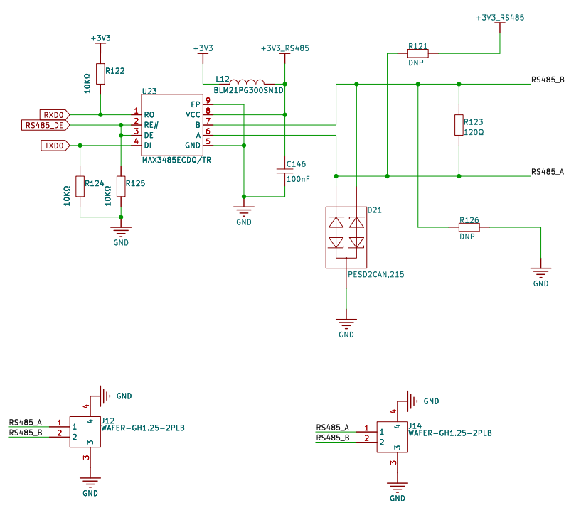
Hardware Description
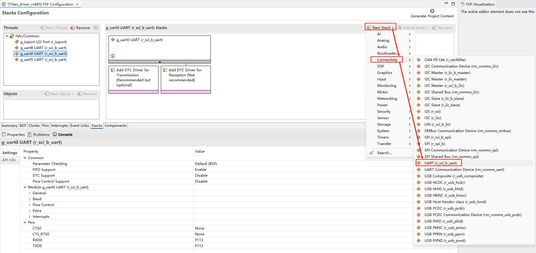
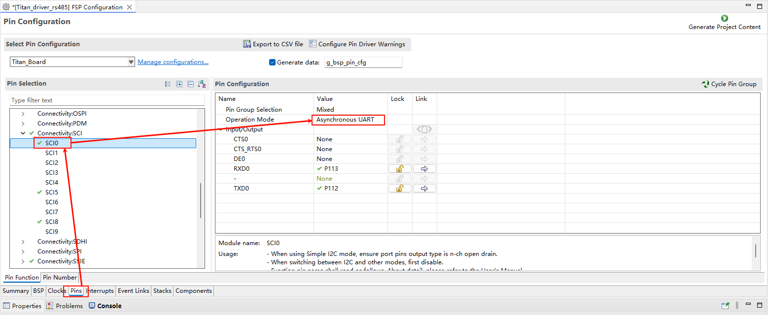
FSP Configuration
Open the FSP tool and create a
r_sci_b_uartstack:
Configure
r_sci_b_uartstack:
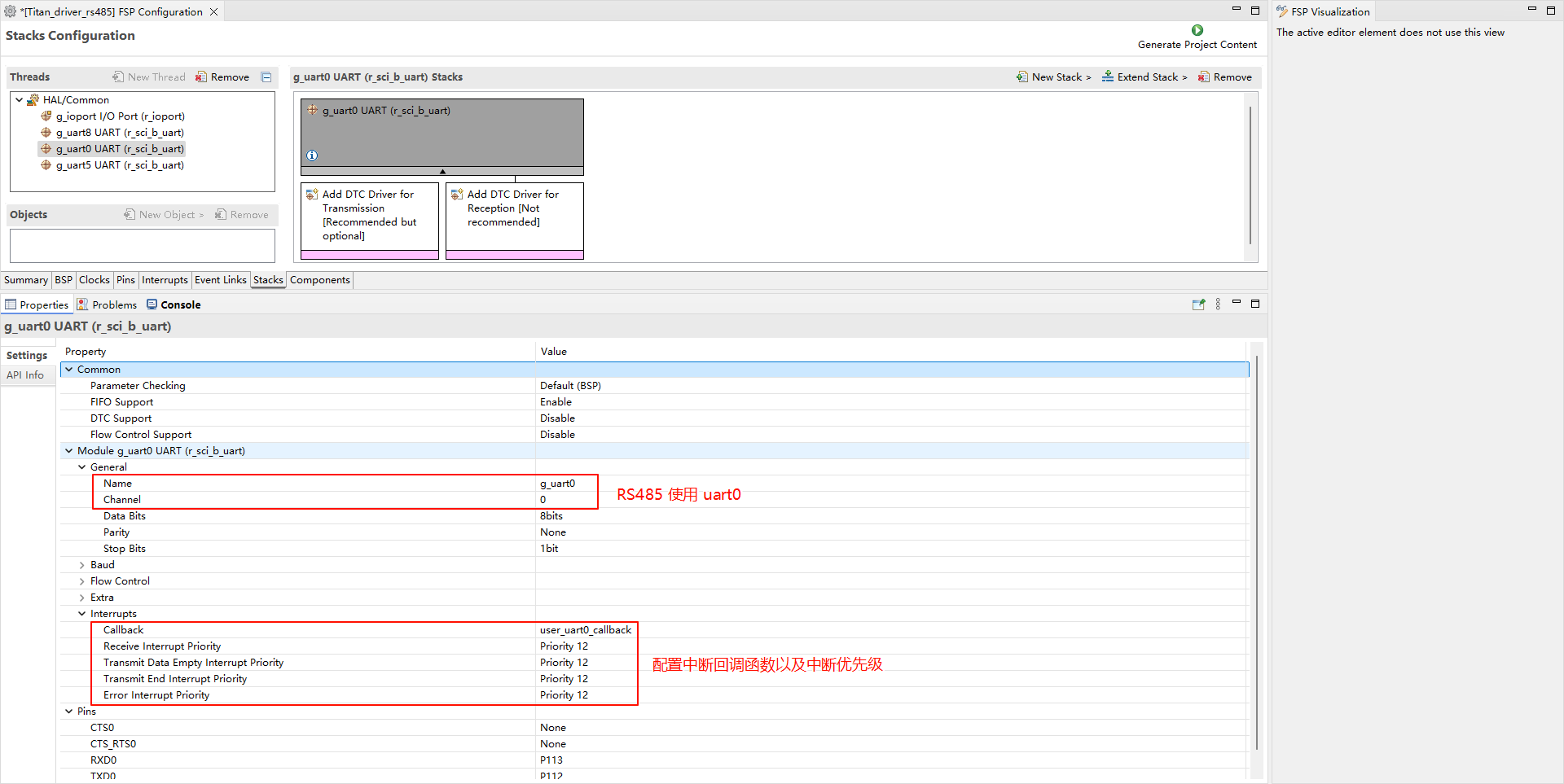
Configure
r_sci_b_uart引脚:
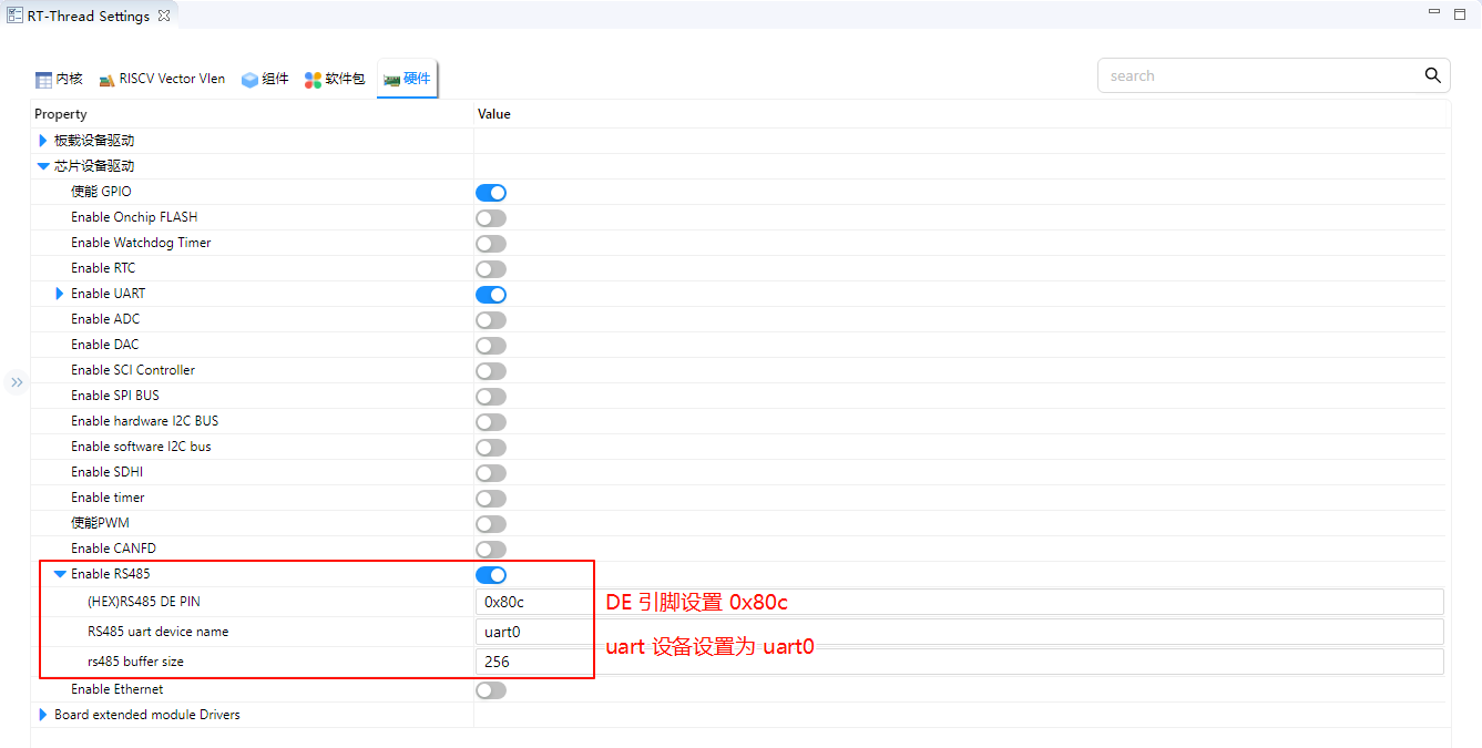
RT-Thread Settings Configuration
Enable and configure RS485.
Example Code Description
#define RS485_OUT       rt_pin_write((rt_base_t)RS485_DE_PIN, PIN_HIGH)
#define RS485_IN        rt_pin_write((rt_base_t)RS485_DE_PIN, PIN_LOW)

static rt_device_t rs485_serial = RT_NULL;
static struct rt_semaphore rs485_rx_sem;
static struct rt_ringbuffer rs485_rx_rb;
static rt_uint8_t rs485_rx_buffer[RS485_RX_BUFFER_SIZE];

/* uart receive data callback function */
static rt_err_t rs485_input(rt_device_t dev, rt_size_t size)
{
    if (size > 0)
    {
        rt_uint8_t ch;
        while (rt_device_read(dev, 0, &ch, 1) == 1)
        {
            rt_ringbuffer_put_force(&rs485_rx_rb, &ch, 1);
        }
        rt_sem_release(&rs485_rx_sem);
    }
    return RT_EOK;
}

/* send data */
int rs485_send_data(const void *tbuf, rt_uint16_t t_len)
{
    RT_ASSERT(tbuf != RT_NULL);

    /* change rs485 mode to transmit */
    RS485_OUT;

    /* send data */
    rt_size_t sent = rt_device_write(rs485_serial, 0, tbuf, t_len);

    if (sent != t_len)
    {
        /* Transmission failed, switch back to receive mode */
        RS485_IN;
        return -RT_ERROR;
    }

    /* Note: We don't switch back to receive mode here -
       that will be done in the tx_complete callback (rs485_output) */

    LOG_I("send==>>");
    for (int i = 0; i < t_len; i++)
    {
        LOG_I("   %d:   %c ", i, ((rt_uint8_t *)tbuf)[i]);
    }
    RS485_IN;

    return RT_EOK;
}

static void rs485_thread_entry(void *parameter)
{
    rt_uint8_t ch;
    rt_size_t length;

    while (1)
    {
        /* Wait for data */
        rt_sem_take(&rs485_rx_sem, RT_WAITING_FOREVER);

        /* Process all available data in the ring buffer */
        while (length = rt_ringbuffer_get(&rs485_rx_rb, &ch, 1))
        {
            if (length == 1)
            {
                LOG_I("recv data:%c", ch);
            }
        }
    }
}

int rs485_init(void)
{
    /* Initialize ring buffer */
    rt_ringbuffer_init(&rs485_rx_rb, rs485_rx_buffer, RS485_RX_BUFFER_SIZE);

    /* find uart device */
    rs485_serial = rt_device_find(RS485_UART_DEVICE_NAME);
    if (!rs485_serial)
    {
        LOG_E("find %s failed!", RS485_UART_DEVICE_NAME);
        return -RT_ERROR;
    }

    /* Open device in interrupt mode with DMA support if available */
    rt_device_open(rs485_serial, RT_DEVICE_FLAG_INT_RX | RT_DEVICE_FLAG_DMA_RX);

    /* set receive data callback function */
    rt_device_set_rx_indicate(rs485_serial, rs485_input);

    /* Initialize RTS pin */
    rt_pin_mode((rt_base_t)RS485_DE_PIN, PIN_MODE_OUTPUT);
    RS485_IN;

    /* Initialize semaphore */
    rt_sem_init(&rs485_rx_sem, "rs485_rx_sem", 0, RT_IPC_FLAG_FIFO);

    rt_thread_t thread = rt_thread_create("rs485", rs485_thread_entry, RT_NULL,
                                        1024, 25, 10);

    if (thread != RT_NULL)
    {
        rt_thread_startup(thread);
    }
    else
    {
        return -RT_ERROR;
    }

    return RT_EOK;
}
INIT_DEVICE_EXPORT(rs485_init);
Build & Download
RT-Thread Studio: Download the Titan Board resource pack from the RT-Thread Studio package manager, then create a new project and compile it.
Once compiled, connect the development board’s USB-DBG interface to the PC, and download the firmware to the development board.
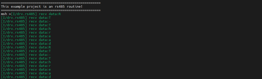
Running Result
Type rs485_cmd -t RT-Thread command in terminal to send “RT-Thread” string.
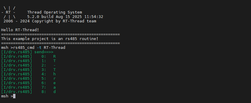
The RS485 interface of the Titan Board is connected to the RS485 interface of another development Board, and the data is continuously sent using the other development board, and the terminal will output the data received by the Titan Board.