BMI088 Gyroscope Usage Instructions
English | Chinese
Introduction
This example demonstrates how to use the SPI module of the RA8 series MCU on the Titan Board, in combination with the RT-Thread SPI driver framework and the BMI088 software package (a 6-axis IMU: 3-axis accelerometer + 3-axis gyroscope), to perform sensor initialization and data acquisition.
Overview of BMI088
1. General Description
The BMI088 is a high-performance 6-axis IMU (Inertial Measurement Unit) developed by Bosch Sensortec, integrating a 3-axis accelerometer and a 3-axis gyroscope.
It is designed for drones, robotics, industrial automation, and navigation systems, where high stability and low noise are required.
The BMI088 is well known for its high vibration robustness and low noise performance. Compared with common consumer-grade IMUs (such as MPU6050, BMI160, etc.), it is more widely used in industrial and UAV applications.
2. Key Features
(1) Accelerometer
Measurement range: ±3 g / ±6 g / ±12 g / ±24 g
Noise density: approx. 120 µg/√Hz
Sampling rate: up to 1.6 kHz
Offset: factory calibrated
Features: high stability, low noise, wide dynamic range
(2) Gyroscope
Measurement range: ±125 °/s, ±250 °/s, ±500 °/s, ±1000 °/s, ±2000 °/s
Noise density: approx. 0.014 °/s/√Hz
Sampling rate: up to 2 kHz
Built-in vibration suppression design to reduce the impact of high-frequency vibration
Excellent bias stability, suitable for long-term operation
(3) Interface & Power Supply
Communication interface: SPI (up to 10 MHz), I²C (up to 400 kHz)
Operating voltage: 1.71V ~ 3.6V
Package: 3 mm × 4.5 mm × 0.95 mm (LGA-16)
3. Working Principle
Accelerometer: Detects acceleration in three axes using MEMS structures and outputs corresponding digital signals.
Gyroscope: Measures angular velocity based on the Coriolis effect, providing three-axis rotational motion data.
Sensor Fusion: Combining accelerometer and gyroscope data allows for attitude estimation (Pitch, Roll, Yaw).
4. Main Advantages
High vibration robustness
The gyroscope features a special anti-vibration structure, making it suitable for drones and other high-vibration environments.
Low-noise performance
Both accelerometer and gyroscope deliver low-noise output, ensuring accurate attitude estimation.
Industrial-grade reliability
More stable and less temperature drift compared to consumer-grade IMUs (e.g., BMI160, MPU6050).
High bandwidth
The gyroscope bandwidth can reach up to 2 kHz, making it ideal for high-speed control scenarios.
5. Application Scenarios
Drones: flight attitude detection, navigation, and stabilization
Robotics: motion control, SLAM, and balance control
Industrial measurement: platform stabilization, robotic arm motion detection
Automotive systems: inertial navigation, assisted positioning
Motion tracking: VR/AR, wearable devices
RA8 Series SPI Module (r_spi_b) Instructions
The RA8 series MCU integrates an enhanced SPI module (r_spi_b), which can be used for high-speed serial communication with peripherals such as Flash memory, sensors, displays, and audio codecs. This module supports both master and slave modes, provides full-duplex communication, and integrates rich buffering, clock control, and DMA mechanisms at the hardware level, effectively reducing CPU workload.
1. Key Features
Operating Modes
Supports Master mode and Slave mode
Supports Full-duplex communication (simultaneous transmit and receive)
Supports Half-duplex mode for unidirectional communication devices
Clock Features
Supports serial clock (SPCLK) up to 166 MHz (depending on system clock and device specifications)
Configurable polarity (CPOL) and phase (CPHA), supporting standard SPI Modes 0/1/2/3
Data Format
Supports 8-bit, 16-bit, and 32-bit frame formats
Supports MSB-first and LSB-first transmission
Chip Select Management
Supports hardware chip select (SSL0~SSL3)
Also supports software-controlled GPIO chip select
Buffering & DMA
Built-in FIFO buffers to reduce interrupt frequency
Supports DTC/DMA automatic transfer, ideal for large data transactions
Interrupts & Events
Transmit complete interrupt
Receive complete interrupt
Transfer error interrupt (e.g., overflow, underrun)
2. SPI Module Architecture
The RA8 series SPI (r_spi_b) consists of the following submodules:
Clock Control Unit
Generates the serial clock (SPCLK)
Configurable prescalers for adjusting communication speed
Provides polarity (CPOL) and phase (CPHA) settings
Transfer Control Unit
Controls data frame length (8/16/32-bit)
Configures data order (MSB/LSB)
Manages transmit/receive direction
FIFO Buffers
Transmit FIFO
Receive FIFO
Reduce interrupt frequency, improve performance
Chip Select Control Unit
Provides up to 4 independent chip select signals (SSL0~SSL3)
Automatic assertion/deassertion of chip select
Supports multiple slave devices
DMA/DTC Support
SPI module can directly cooperate with DMA/DTC
Enables CPU-free streaming data transfer
Especially useful for sensor data acquisition, external memory access, etc.
Interrupt Control
Transmit interrupt (TXI)
Receive interrupt (RXI)
Transfer end interrupt (TEI)
Error interrupt (ERI)
3. Working Principle
Master Mode Communication
Configure SPCLK, CPOL, and CPHA
Configure chip select signal (SSLx)
Write data into transmit FIFO
SPI hardware automatically shifts out data while receiving incoming data
Slave Mode Communication
Wait for chip select signal from master
Receive data from master while optionally transmitting response data
Supports DMA for writing received data into memory
FIFO & DMA Coordination
Short transfers: handled via interrupts
Large data transfers: automatically handled via DMA/DTC, CPU only needs to configure initial parameters
RT-Thread SPI Driver Framework
The RT-Thread SPI (Serial Peripheral Interface) framework is a unified interface provided by the RT-Thread device driver layer to manage SPI peripherals across different MCUs. It abstracts low-level hardware register operations, allowing applications to communicate with SPI slave devices via standardized APIs in an efficient, reliable, and portable way.
1. Device Model
In RT-Thread, the SPI system consists of buses and devices. SPI devices are managed as device objects (subclass of struct rt_device, type RT_Device_Class_SPIBUS or RT_Device_Class_SPIDevice). Developers do not need to access hardware registers directly — all send, receive, and chip-select operations can be performed through standard RT-Thread SPI APIs.
2. Operation Interfaces
Applications interact with SPI devices through RT-Thread’s device management interfaces. Common APIs include:
Find SPI device
rt_device_t rt_device_find(const char* name);
Custom message transfer
struct rt_spi_message *rt_spi_transfer_message(struct rt_spi_device *device,
                                               struct rt_spi_message *message);
This function allows transferring a sequence of messages.
Users can define multiple message structures to precisely control chip-select behavior and transfer sequence.
The struct rt_spi_message is defined as follows:
struct rt_spi_message
{
    const void *send_buf;           /* Send buffer pointer */
    void *recv_buf;                 /* Receive buffer pointer */
    rt_size_t length;               /* Number of bytes to transfer */
    struct rt_spi_message *next;    /* Pointer to next message */
    unsigned cs_take    : 1;        /* Chip select active */
    unsigned cs_release : 1;        /* Chip select release */
};
Transfer a single block of data
rt_size_t rt_spi_transfer(struct rt_spi_device *device,
                          const void           *send_buf,
                          void                 *recv_buf,
                          rt_size_t             length);
Send-only transfer (ignore received data)
rt_size_t rt_spi_send(struct rt_spi_device *device,
                      const void           *send_buf,
                      rt_size_t             length);
Receive-only transfer
rt_size_t rt_spi_recv(struct rt_spi_device *device,
                      void                 *recv_buf,
                      rt_size_t             length);
Send two buffers continuously (without releasing chip select)
rt_err_t rt_spi_send_then_send(struct rt_spi_device *device,
                               const void           *send_buf1,
                               rt_size_t             send_length1,
                               const void           *send_buf2,
                               rt_size_t             send_length2);
Send then receive data (without releasing chip select)
rt_err_t rt_spi_send_then_recv(struct rt_spi_device *device,
                               const void           *send_buf,
                               rt_size_t             send_length,
                               void                 *recv_buf,
                               rt_size_t             recv_length);
3. Framework Features
Unified abstraction: Supports both master and slave communication through standard APIs.
Cross-platform: Portable across different MCU platforms with no code changes.
Flexible chip-select control: Supports single, continuous, and combined transfer modes.
Message chaining: Enables complex multi-message transfers via
rt_spi_message.High extensibility: Easily integrates with DMA or RT-Thread IPC mechanisms for better performance.
Reference: RT-Thread SPI Device
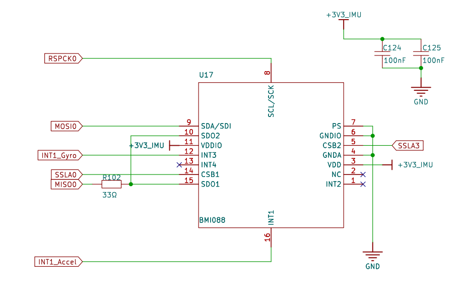
Hardware Description
The Titan Board uses SPI0 to communicate with the BMI088 gyroscope.
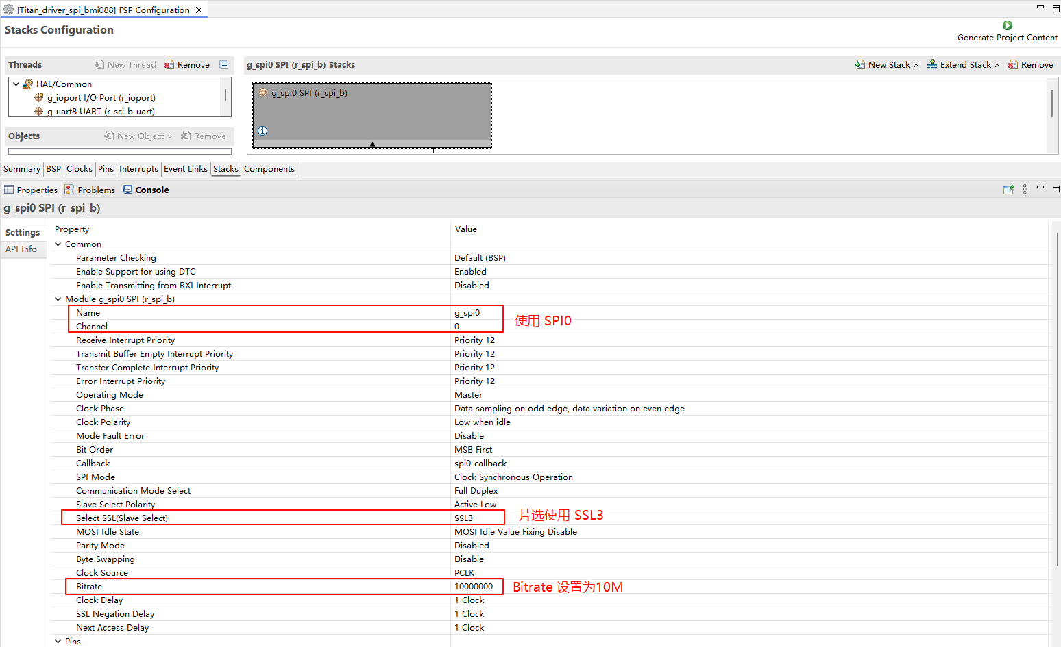
FSP Configuration
Open the FSP tool, create a new stack, and select
r_spi_b:
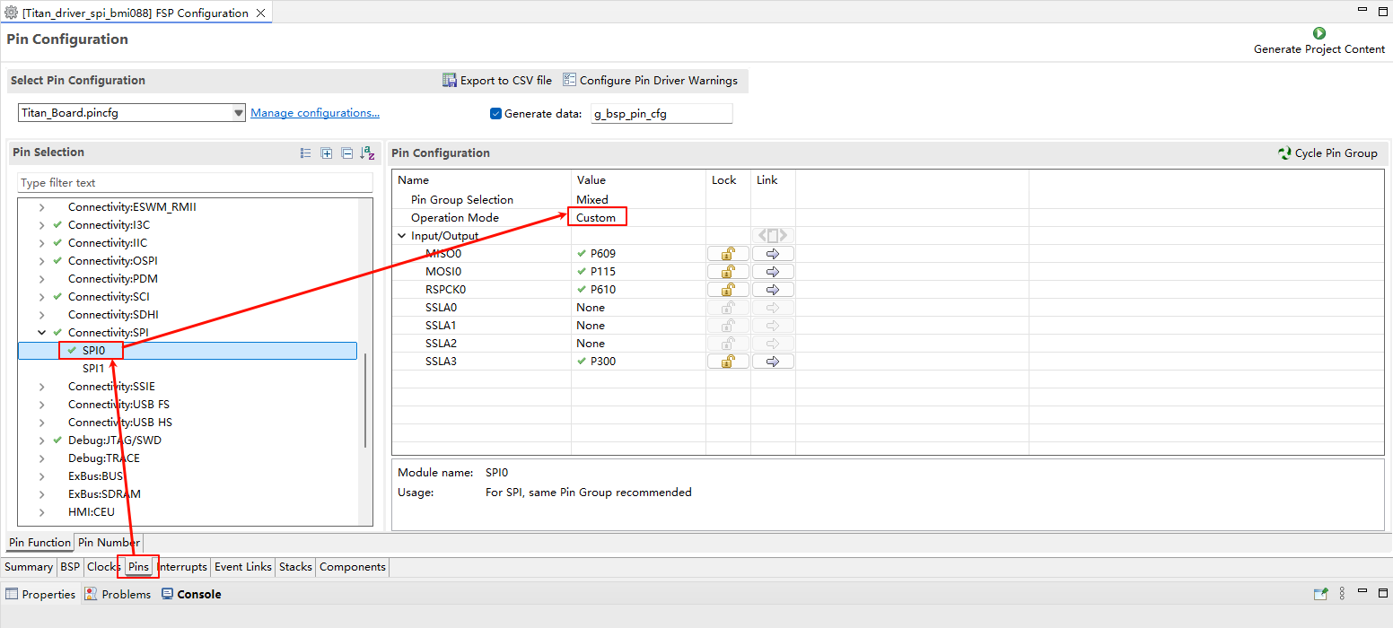
Configure SPI0 pins:
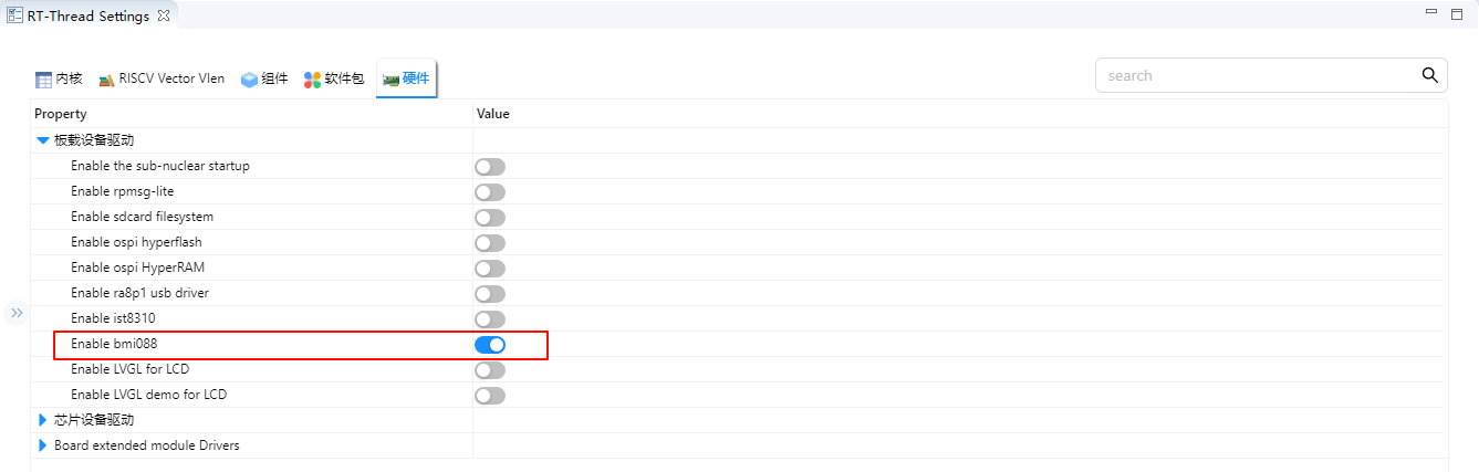
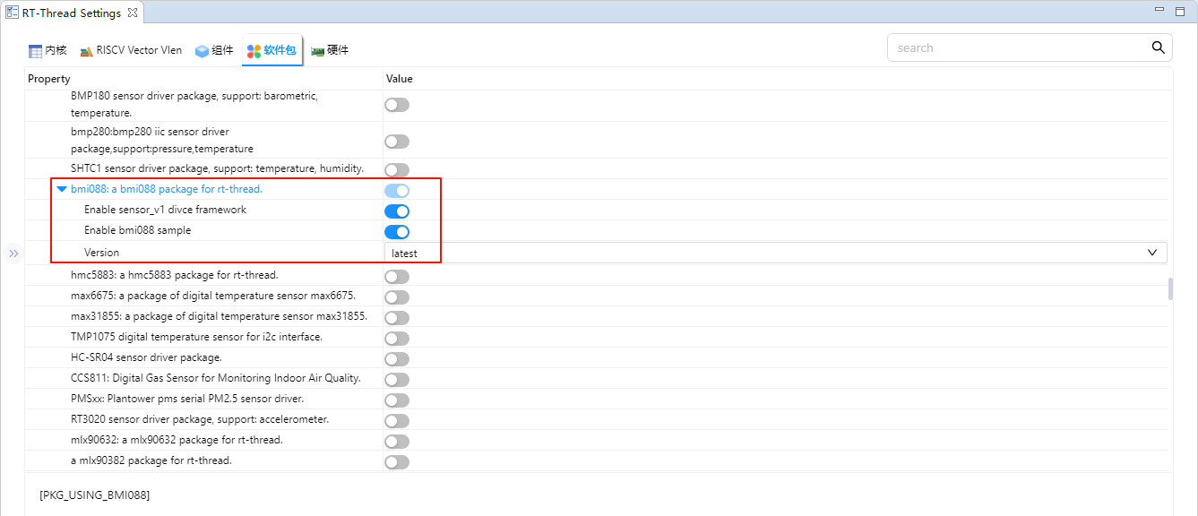
RT-Thread Settings Configuration
Enable bmi088:
Enable sensor_v1 and sample in the bmi088 package configuration:
Software Description
Using the BMI088 package on the Titan Board requires the following modifications for adaptation:
Modify
./packages/bmi088-latest/sample/bmi088_sample.c:
Modify the SPI BUS to spi0, and modify the chip selection pin:
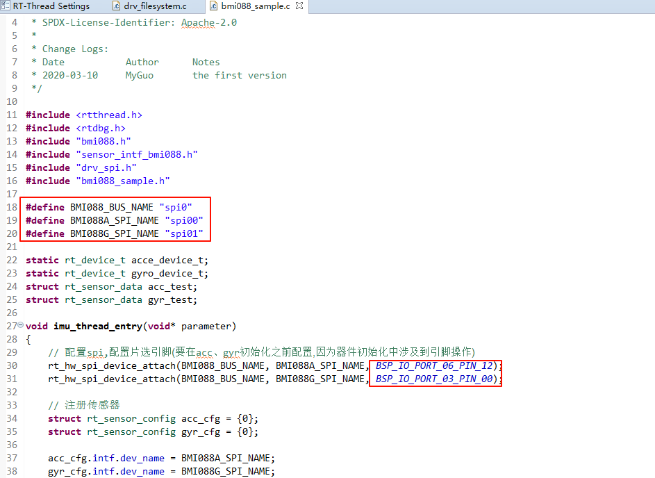
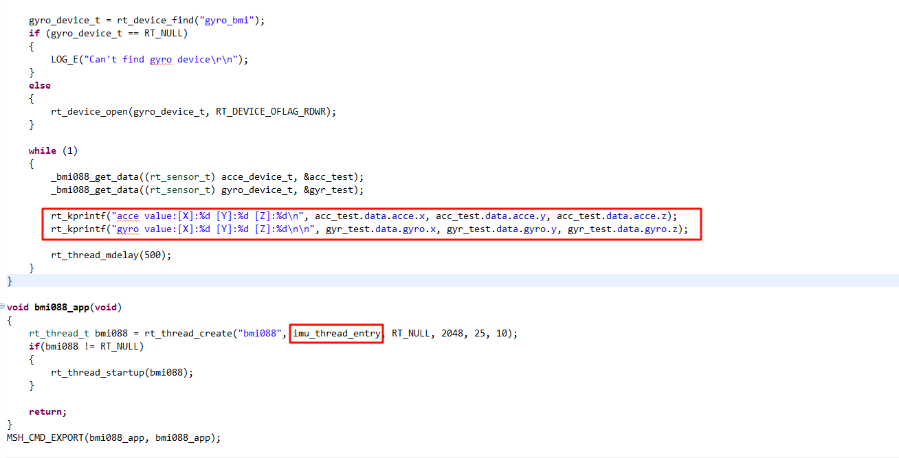
Add imu data printing and create a data ingest thread:
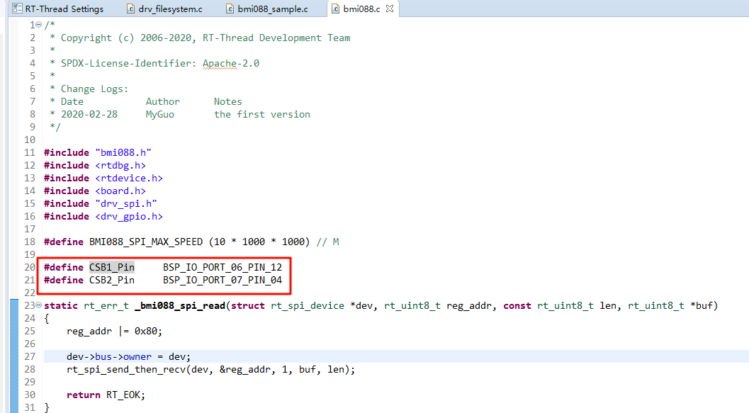
Modify
./packages/bmi088-latest/src/bmi088.c
Modify the CS pin adaptation Renesas development board:
The bmi088 driver sample is located at ./packages/bmi088-latest/samples/bmi088_sample:
/*
 * Copyright (c) 2006-2020, RT-Thread Development Team
 *
 * SPDX-License-Identifier: Apache-2.0
 *
 * Change Logs:
 * Date           Author      Notes
 * 2020-03-10     MyGuo       the first version
 */

#include <rtthread.h>
#include <rtdbg.h>
#include "bmi088.h"
#include "sensor_intf_bmi088.h"
#include "drv_spi.h"
#include "bmi088_sample.h"

#define BMI088_BUS_NAME "spi0"
#define BMI088A_SPI_NAME "spi00"
#define BMI088G_SPI_NAME "spi01"

static rt_device_t acce_device_t;
static rt_device_t gyro_device_t;
struct rt_sensor_data acc_test;
struct rt_sensor_data gyr_test;

void imu_thread_entry(void* parameter)
{
    // Configure spi, configure chip selection pin (before acc, gyr initialization, because device initialization involves pin operation)
    rt_hw_spi_device_attach(BMI088_BUS_NAME, BMI088A_SPI_NAME, BSP_IO_PORT_06_PIN_12);
    rt_hw_spi_device_attach(BMI088_BUS_NAME, BMI088G_SPI_NAME, BSP_IO_PORT_07_PIN_04);

    // Registering sensors
    struct rt_sensor_config acc_cfg = {0};
    struct rt_sensor_config gyr_cfg = {0};

    acc_cfg.intf.dev_name = BMI088A_SPI_NAME;
    gyr_cfg.intf.dev_name = BMI088G_SPI_NAME;

    rt_hw_bmi088_init("bmi", &acc_cfg, &gyr_cfg);

    acce_device_t = rt_device_find("acce_bmi");
    if (acce_device_t == RT_NULL)
    {
        LOG_E("Can't find acce device\r\n");
    }
    else
    {
        rt_device_open(acce_device_t, RT_DEVICE_OFLAG_RDWR);
    }

    gyro_device_t = rt_device_find("gyro_bmi");
    if (gyro_device_t == RT_NULL)
    {
        LOG_E("Can't find gyro device\r\n");
    }
    else
    {
        rt_device_open(gyro_device_t, RT_DEVICE_OFLAG_RDWR);
    }

    while (1)
    {
        _bmi088_get_data((rt_sensor_t) acce_device_t, &acc_test);
        _bmi088_get_data((rt_sensor_t) gyro_device_t, &gyr_test);

        rt_kprintf("acce value:[X]:%d [Y]:%d [Z]:%d\n", acc_test.data.acce.x, acc_test.data.acce.y, acc_test.data.acce.z);
        rt_kprintf("gyro value:[X]:%d [Y]:%d [Z]:%d\n\n", gyr_test.data.gyro.x, gyr_test.data.gyro.y, gyr_test.data.gyro.z);

        rt_thread_mdelay(1000);
    }
}

void bmi088_app(void)
{
    rt_thread_t bmi088 = rt_thread_create("bmi088", imu_thread_entry, RT_NULL, 2048, 25, 10);
    if(bmi088 != RT_NULL)
    {
        rt_thread_startup(bmi088);
    }

    return;
}
MSH_CMD_EXPORT(bmi088_app, bmi088_app);
Compilation & Download
RT-Thread Studio: In RT-Thread Studio’s package manager, download the Titan Board resource package, create a new project, and compile it.
After compilation, connect the development board’s USB-DBG interface to the PC and download the firmware to the development board.
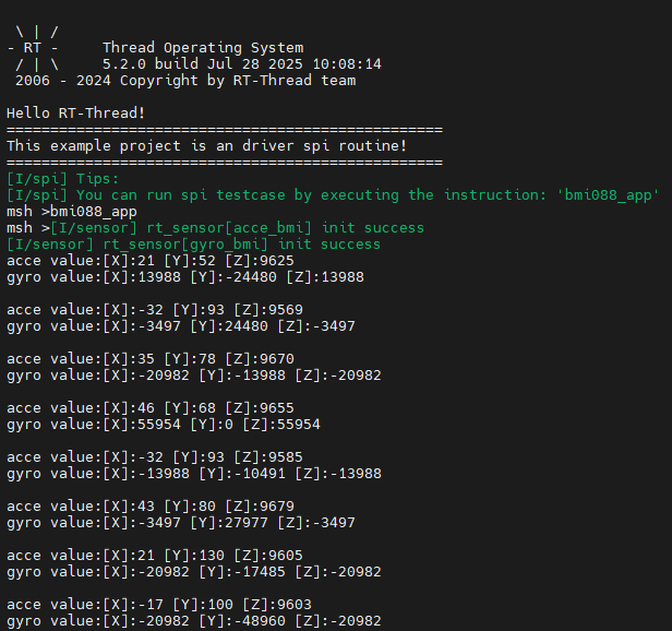
Run Effect
Open the serial port tool and enter the bmi088_app command in the terminal to obtain the gyroscope data: