GPT Usage Guide
English | Chinese
Introduction
In our specific application scenarios, the use of timers is often indispensable. This example mainly introduces how to use the GPT device on the Titan Board, including the basic timer usage and PWM usage.
PWM Introduction
PWM (Pulse Width Modulation) is a method of digitally encoding the level of an analog signal. By generating pulses at different frequencies and varying the duty cycle of a square wave, PWM encodes the level of a specific analog signal. The output produces a series of pulses with equal amplitude, and these pulses can be used by devices to approximate the desired waveform.

The figure above illustrates a simple principle of PWM. Assume the timer is operating in up-counting mode:
When the counter value is less than the threshold, the output is in one logic state (e.g., high level).
When the counter value exceeds the threshold, the output switches to the opposite logic state (e.g., low level).
Once the counter reaches its maximum value, it resets to 0 and begins counting again, returning to the initial logic state.
The ratio of the high-level duration (pulse width) to the total period is called the duty cycle, which ranges from 0% to 100%. In the example shown above, the high level lasts exactly half of the period, so the duty cycle is 50%.
A common use case for PWM is controlling the brightness of lights or displays. By adjusting the duty cycle, the brightness can be controlled. PWM does not keep the light continuously on; instead, it repeatedly turns the screen on and off at high speed. When the on/off switching is fast enough, the human eye perceives it as a constant light. During this cycle, if the off duration is longer, the screen appears dimmer. Conversely, if the on duration is longer, the screen appears brighter.

Timer Introduction
1. Overview
A Timer is a hardware module in microcontrollers (MCUs) or embedded systems that is used to generate precise time intervals or count events. A timer typically can:
Generate interrupts at fixed intervals
Measure time duration or event intervals
Drive PWM signal generation
Count external pulses
Timers are core modules for MCU real-time control, PWM output, event counting, periodic sampling, and more.
2. Types of Timers
Depending on their functionality and applications, timers can be categorized into the following types:
Basic Timer
A simple counter, mainly used for generating fixed interval interrupts
Usually supports only up-counting
General Purpose Timer (GPT)
Supports multiple modes: one-shot counting, periodic counting, PWM output, input capture
Configurable prescaler, counting mode, and auto-reload value
Advanced Timer
Provides more complex features such as dead-time insertion, synchronization triggers, and complementary PWM output
Commonly used in motor control and power electronics applications
Watchdog Timer
Used for system reliability monitoring
If the MCU fails to reset the timer within a given time, a system reset or interrupt will be triggered
Real-Time Clock (RTC) Timer
Provides calendar/clock functions
Low-power, continues timing in standby mode
3. Working Principle of Timers
A timer usually consists of the following components:
Counter
Used to accumulate or decrement count values
Counting unit is determined by the Timer Clock Frequency
Prescaler
Divides the system clock to slow down the counter frequency
Formula:
Timer Tick Frequency = Timer Clock / (Prescaler + 1)
Auto-Reload Register (ARR / Period Register)
When the counter reaches this value, it triggers an interrupt or event
Enables cyclic counting
Interrupt/Event Generation
When the counter matches ARR, it can trigger interrupts, update PWM, or generate external events
4. Timer Modes
One-Shot Mode
Counter stops after reaching the target value
Used for single delays or event triggering
Continuous / Auto-Reload Mode
Counter automatically reloads after reaching the target value and continues counting
Used for periodic timers and PWM output
PWM Mode
Uses a compare register to generate PWM signals with adjustable duty cycles
Widely used in motor control, LED dimming
Input Capture Mode
Captures timestamps of external signal edges
Used to measure pulse width, frequency, or event intervals
Output Compare Mode
Changes output state when the counter matches the compare value
Used for timed event triggering or waveform generation
RA8 Series GPT Module Overview
The Renesas RA8 series microcontrollers integrate a high-performance General Purpose Timer (GPT) module that supports multiple timing and control features suitable for various application scenarios.
GPT Module Features
Supported Modes: Periodic mode, One-shot mode, and PWM mode
Counting Sources: Supports PCLK, external trigger pins (GTETRG), GTIOC pins, or ELC events
PWM Output: Supports output of periodic or PWM signals through GTIOC pins
Reconfigurable: Supports runtime reconfiguration of period, duty cycle, and compare values
Counting Direction: Supports up-counting, down-counting, or up/down counting
High Resolution: Supports high-resolution PWM waveform generation, suitable for precision control applications
RT-Thread PWM Framework Introduction
The RT-Thread PWM (Pulse Width Modulation) framework is a unified interface provided by the RT-Thread device driver layer to manage PWM hardware modules across various MCUs. This framework abstracts the underlying PWM functionality into a standardized device interface, allowing applications to configure period and pulse width through a uniform API and achieve cross-platform PWM control.
1. Device Model
In RT-Thread, PWM is managed as a device object (subclass of struct rt_device, type RT_Device_Class_PWM). Developers do not need to manipulate hardware registers directly. PWM channel configuration, enabling, and disabling can all be performed via the standard RT-Thread device interface.
2. Operation Interfaces
Applications access PWM devices through RT-Thread’s I/O device management interfaces. Key APIs include:
Find PWM device
rt_device_t rt_device_find(const char* name);
Set PWM period and pulse width
rt_err_t rt_pwm_set(struct rt_device_pwm *device, int channel, rt_uint32_t period, rt_uint32_t pulse);
Enable PWM channel
rt_err_t rt_pwm_enable(struct rt_device_pwm *device, int channel);
Disable PWM channel
rt_err_t rt_pwm_disable(struct rt_device_pwm *device, int channel);
3. Framework Features
Unified Interface: All PWM hardware modules are accessed through the same interface, simplifying application development.
Cross-Platform Support: Applications can be ported across different MCU platforms without modifying PWM code.
Flexible Channel Control: Supports independent configuration, enabling, and disabling of multiple channels.
Accurate Control: Configurable period and pulse width for high-precision PWM output.
High Extensibility: Can be combined with timers, DMA, and other modules for complex control scenarios.
4. Runtime PWM Parameter Adjustment
The RA8 GPT module supports runtime adjustment of PWM period and duty cycle.
Example: Set PWM period to 500000 and duty cycle to 70%:
#define PWM_DEV_NAME    "pwm12"
#define PWM_DEV_CHANNEL 0

struct rt_device_pwm *pwm_dev = RT_NULL;
rt_uint32_t period = 500000;
rt_uint32_t pulse  = 350000;

pwm_dev = (struct rt_device_pwm *)rt_device_find(PWM_DEV_NAME);
rt_pwm_set(pwm_dev, PWM_DEV_CHANNEL, period, pulse);
rt_pwm_enable(pwm_dev, PWM_DEV_CHANNEL);
Reference: RT-Thread PWM Device
RT-Thread Hardware Timer Framework Introduction
The RT-Thread Hardware Timer (hwtimer) framework provides a unified driver interface for MCU hardware timers. It enables high-precision timing control, making it suitable for periodic task scheduling, event timing, and PWM triggering. Through the hwtimer framework, developers can control timer start/stop, mode configuration, callback setup, and value reading via standardized APIs.
1. Device Model
In RT-Thread, hardware timers are managed as device objects (a subclass of struct rt_device, type RT_Device_Class_Timer). Developers don’t need to access hardware registers directly—timer control is done via RT-Thread’s unified device interface.
2. Operation Interfaces
Applications access hwtimer devices via the RT-Thread device management API. Common interfaces include:
Find timer device
rt_device_t rt_device_find(const char* name);
Open timer device (read/write mode)
rt_err_t rt_device_open(rt_device_t dev, rt_uint16_t oflags);
Set timeout callback
rt_err_t rt_device_set_rx_indicate(rt_device_t dev, rt_err_t (*rx_ind)(rt_device_t dev, rt_size_t size));
Control timer (mode/frequency/start/stop)
rt_err_t rt_device_control(rt_device_t dev, rt_uint8_t cmd, void* arg);
Common command macros:
#define HWTIMER_CTRL_FREQ_SET     (0x10)  /* Set timer frequency */
#define HWTIMER_CTRL_MODE_SET     (0x11)  /* Set timer mode */
#define HWTIMER_CTRL_START        (0x12)  /* Start timer */
#define HWTIMER_CTRL_STOP         (0x13)  /* Stop timer */
Set timeout value and start timer
rt_size_t rt_device_write(rt_device_t dev, rt_off_t pos, const void* buffer, rt_size_t size);
Get current timer value
rt_size_t rt_device_read(rt_device_t dev, rt_off_t pos, void* buffer, rt_size_t size);
Close timer device
rt_err_t rt_device_close(rt_device_t dev);
3. Framework Features
Unified Interface: All hardware timers share the same API for control and configuration.
High Precision: Supports microsecond-level timing for real-time applications.
Multiple Modes: Supports both one-shot and periodic timer modes.
Callback Mechanism: Timeout events can trigger user-defined callback functions.
Cross-Platform Compatibility: Applications can be easily ported across MCU platforms.
Reference: RT-Thread HWTIMER Device
Hardware Description
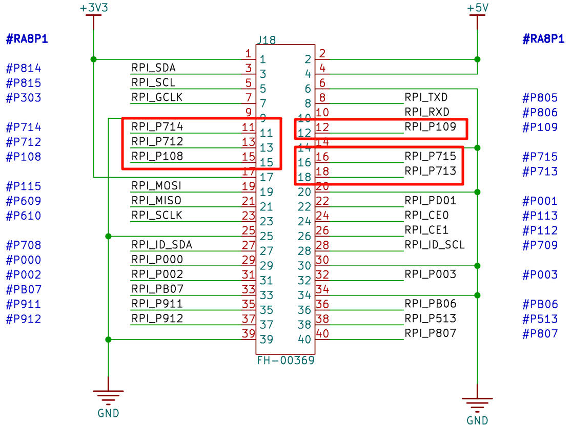
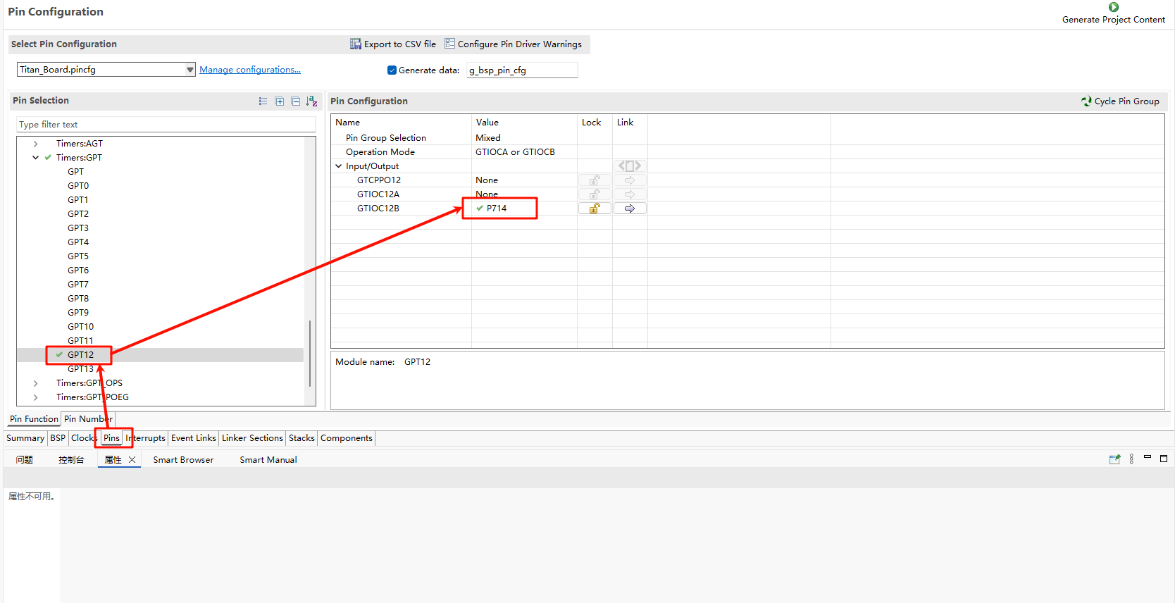
The Raspberry Pi interface of the Titan Board has 6 PWM interfaces. In this example, P714 is used to output PWM waves.
FSP Configuration
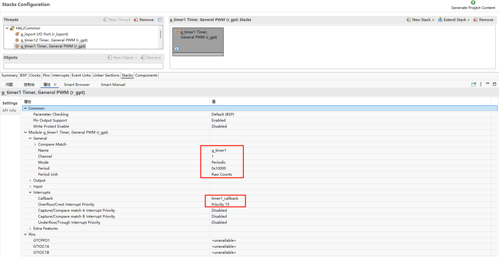
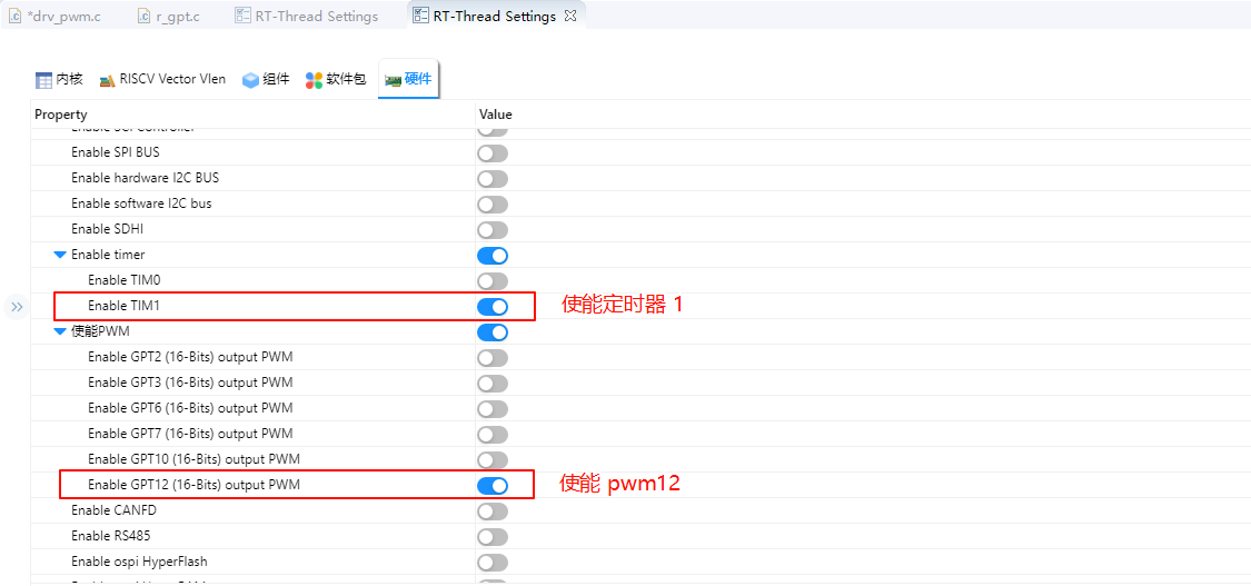
The FSP is configured to enable GPT1 as a basic timer mode and GPT12 as a PWM mode:
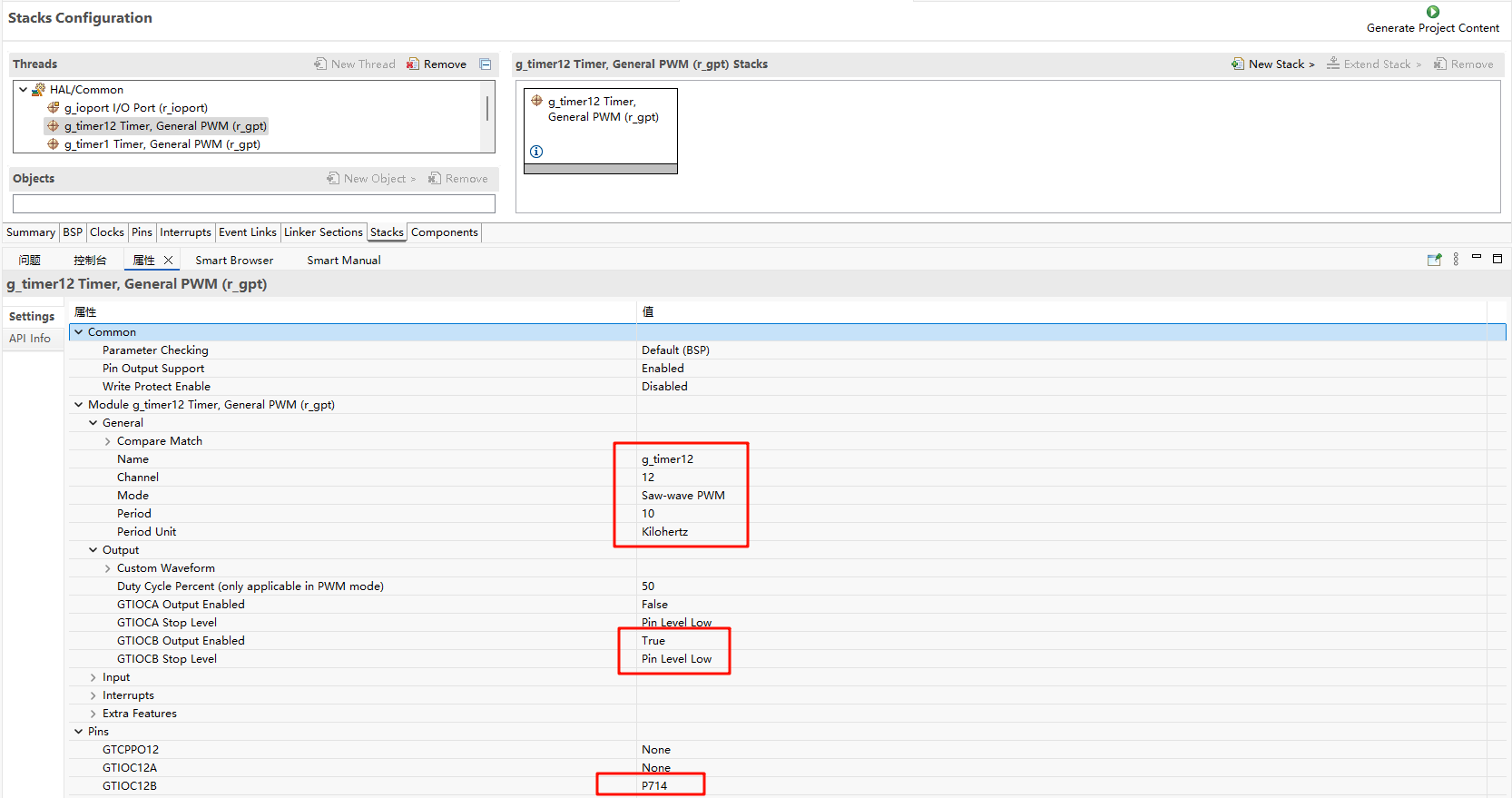
Additionally, the pins for GPT12 are enabled:
RT-Thread Settings Configuration
In the configuration, enable timer1 and PWM12:
Example Project Instructions
The source code for this example is located in /project/Titan_driver_gpt:
/* This is a hwtimer example */
#define HWTIMER_DEV_NAME "timer1" /* device name */
static rt_err_t timeout_cb(rt_device_t dev, rt_size_t size)
{
    rt_kprintf("this is hwtimer timeout callback fucntion!\n");
    rt_kprintf("tick is :%d !\n", rt_tick_get());
    return RT_EOK;
}

int hwtimer_sample(void)
{
    rt_err_t ret = RT_EOK;
    rt_hwtimerval_t timeout_s;
    rt_device_t hw_dev = RT_NULL;
    rt_hwtimer_mode_t mode;

    rt_uint32_t freq = R_FSP_SystemClockHzGet(FSP_PRIV_CLOCK_PCLKD) >> g_timer1_cfg.source_div;
    rt_kprintf("GPT Timer clock freq is: %d hz\n", freq);

    hw_dev = rt_device_find(HWTIMER_DEV_NAME);
    if (hw_dev == RT_NULL)
    {
        rt_kprintf("hwtimer sample run failed! can't find %s device!\n", HWTIMER_DEV_NAME);
        return -RT_ERROR;
    }

    ret = rt_device_open(hw_dev, RT_DEVICE_OFLAG_RDWR);
    if (ret != RT_EOK)
    {
        rt_kprintf("open %s device failed!\n", HWTIMER_DEV_NAME);
        return ret;
    }

    rt_device_set_rx_indicate(hw_dev, timeout_cb);

    rt_device_control(hw_dev, HWTIMER_CTRL_FREQ_SET, &freq);

    mode = HWTIMER_MODE_PERIOD;
    ret = rt_device_control(hw_dev, HWTIMER_CTRL_MODE_SET, &mode);
    if (ret != RT_EOK)
    {
        rt_kprintf("set mode failed! ret is :%d\n", ret);
        return ret;
    }

    /* Example Set the timeout period of the timer */
    timeout_s.sec = 1;  /* secend */
    timeout_s.usec = 0; /* microsecend */
    if (rt_device_write(hw_dev, 0, &timeout_s, sizeof(timeout_s)) != sizeof(timeout_s))
    {
        rt_kprintf("set timeout value failed\n");
        return -RT_ERROR;
    }

    /* read hwtimer value */
    rt_device_read(hw_dev, 0, &timeout_s, sizeof(timeout_s));
    rt_kprintf("Read: Sec = %d, Usec = %d\n", timeout_s.sec, timeout_s.usec);

    return ret;
}
MSH_CMD_EXPORT(hwtimer_sample, hwtimer sample);
The interrupt callback function is triggered every 1 second, printing output. Below is the PWM configuration and enablement:
PWM-related macros:
The current version of the PWM driver treats each channel as a separate PWM device, with each device having only one channel (channel 0). Using the PWM12 device, note that channel 0 is selected here:
#define PWM_DEV_NAME        "pwm12" /* PWM device name */
#define PWM_DEV_CHANNEL      0      /* PWM channel */
struct rt_device_pwm *pwm_dev;      /* PWM device handle */
Configure the PWM period and duty cycle:
static int pwm_sample(int argc, char *argv[])
{
rt_uint32_t period, pulse;
if (argc != 3)
{
LOG_I("Usage: pwm_sample <period> <pulse>");
LOG_I("Example: pwm_sample 500000 250000");
return -RT_ERROR;
}
period = (rt_uint32_t)atoi(argv[1]);
pulse = (rt_uint32_t)atoi(argv[2]);
if (period == 0 || pulse > period)
{
LOG_E("Error: Invalid parameters. Ensure period > 0 and pulse <= period.");
return -RT_ERROR;
}
pwm_dev = (struct rt_device_pwm *)rt_device_find(PWM_DEV_NAME);
if (pwm_dev == RT_NULL)
{
LOG_E("Error: Cannot find PWM device named '%s'\n", PWM_DEV_NAME);
return -RT_ERROR;
}
if (rt_pwm_set(pwm_dev, PWM_DEV_CHANNEL, period, pulse) != RT_EOK)
{
LOG_E("Error: Failed to set PWM configuration.");
return -RT_ERROR;
}
if (rt_pwm_enable(pwm_dev, PWM_DEV_CHANNEL) != RT_EOK)
{
LOG_E("Error: Failed to enable PWM output.");
return -RT_ERROR;
}
LOG_I("PWM started on device: %s, channel: %d", PWM_DEV_NAME, PWM_DEV_CHANNEL);
LOG_I("Period: %u ns, Pulse: %u ns", period, pulse);
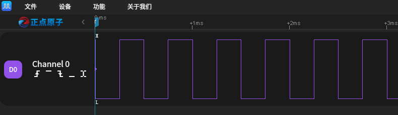
LOG_I("Please connect the \'P714\' to a logic analyzer or oscilloscope for waveform observation.");
return RT_EOK;
}
MSH_CMD_EXPORT(pwm_sample, Configure and start PWM output: pwm_sample <period> <pulse>);
Compilation & Download
RT-Thread Studio: Download the Titan Board resource package in the RT-Thread Studio package manager, then create a new project and compile it.
After compilation, connect the development board’s USB-DBG interface to the PC, and download the firmware to the development board.
Running Results
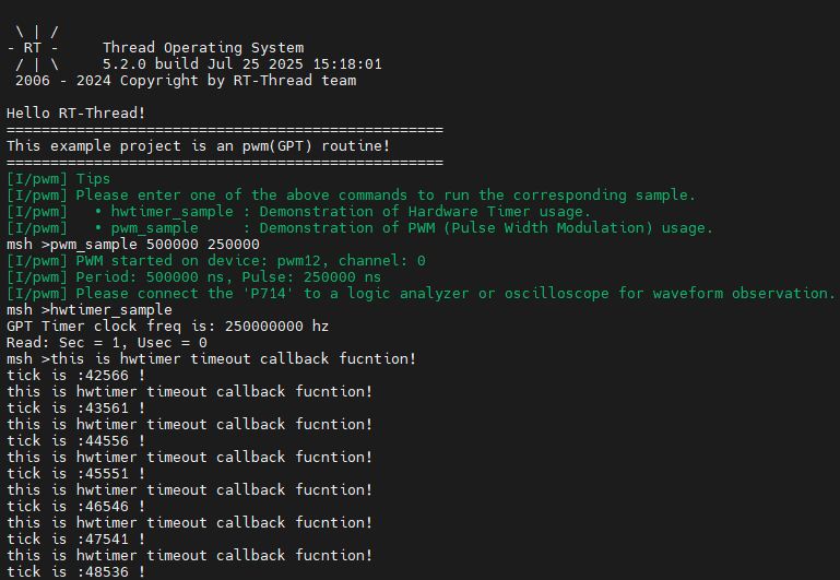
In the serial terminal, input pwm_sample and hwtimer_sample to see the specific results.
The callback function is triggered every 1 second, and the output is printed:
Using a logic analyzer, the PWM output waveform is measured as follows: