Frequently Asked Questions (FAQ)
This document collects common issues encountered by users during usage and provides corresponding solutions.
1. Firmware Programming
Q1. DAP-Link not detected during firmware flashing
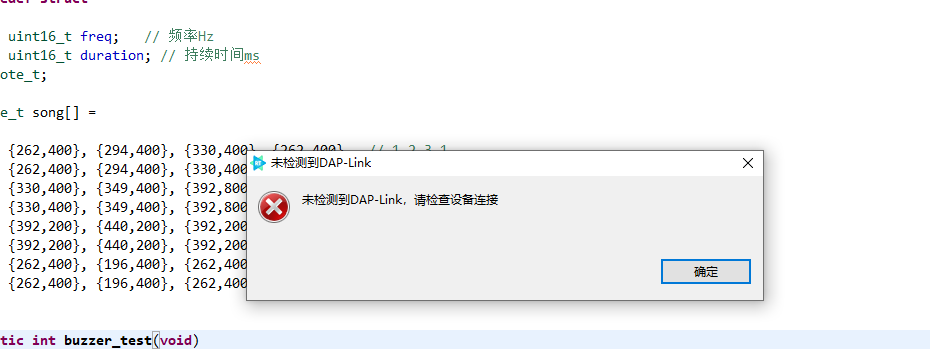
Solution:
Uninstall the WinUSB device in Device Manager, then reconnect the USB cable.
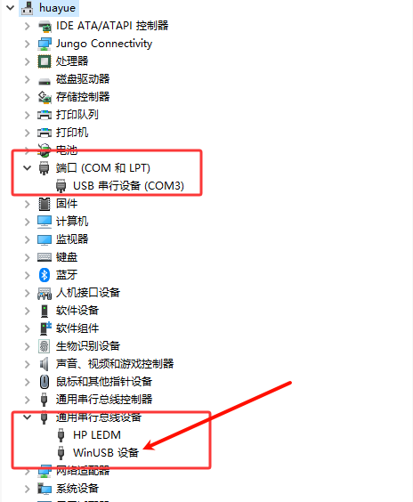
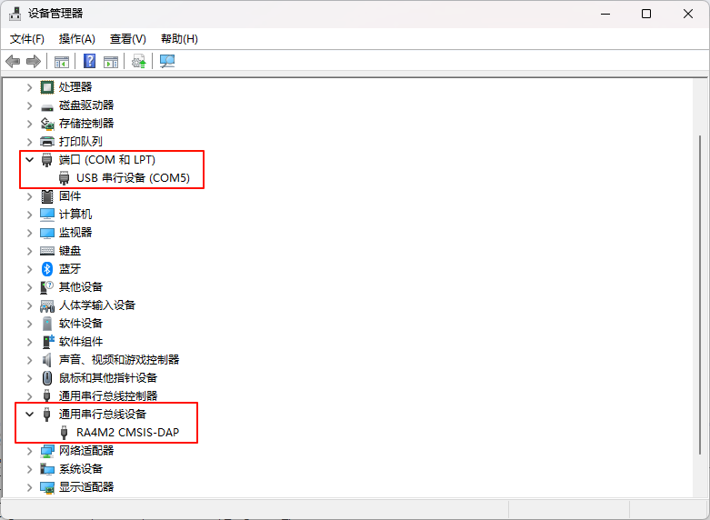
After doing so, both the serial port and CMSIS-DAP devices should appear in Device Manager.
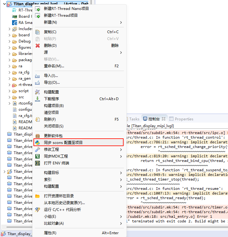
Q2. First compilation error after creating an example project
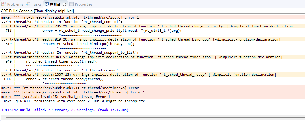
Solution: Right-click the project and select Synchronize scons configuration to project.
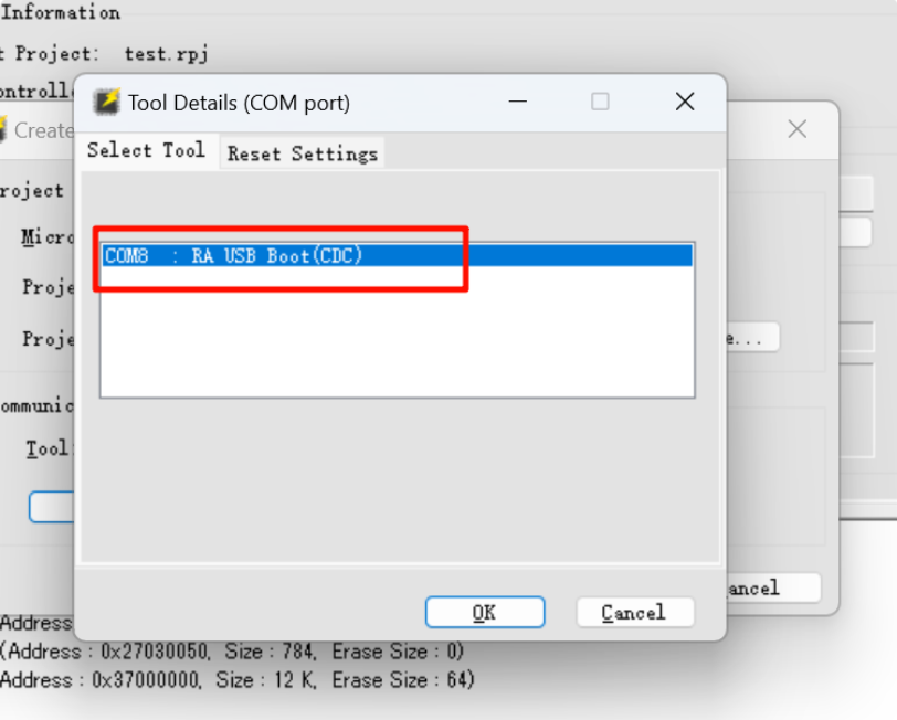
Q3. RFP stuck while creating a new project
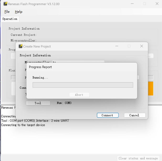
Solution:
Select Tool
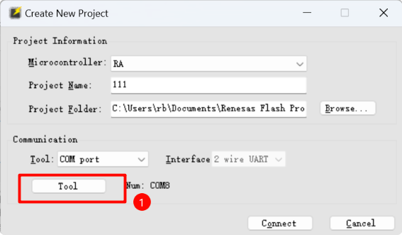
Put the development board into BOOT mode (hold the BOOT button while pressing RST). When the following window appears, click OK to connect.(Do not release the BOOT button until the project is created successfully.)
Q4. Unable to flash HEX file using RFP
Solution:
Connect via the USB port labeled USB-DEV.
Make sure the development board is in BOOT mode.
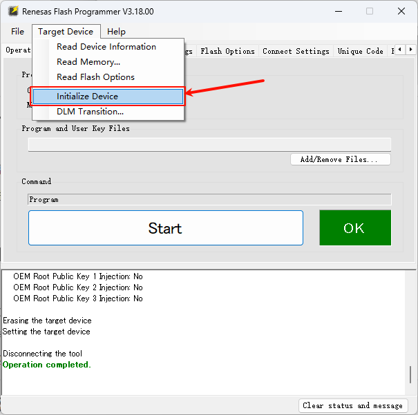
Q5. Chip cannot be programmed
Solution: If the chip cannot be programmed, you can reinitialize it as follows:
Enter BOOT mode, then click Initialize Chip as shown below:
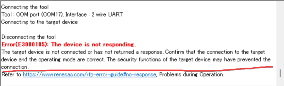
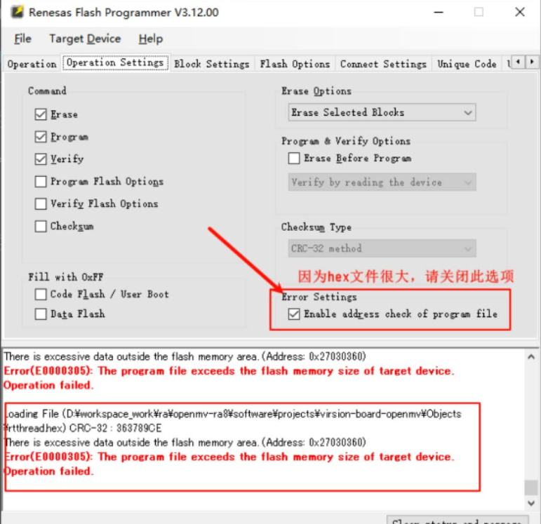
Q6. Error after clicking download:
Error(E0000305): The program file exceeds the flash memory size of target device. Operation failed.
Solution:
Refer to the image below:
Q7. DAP-Link malfunction after flashing dual-core program
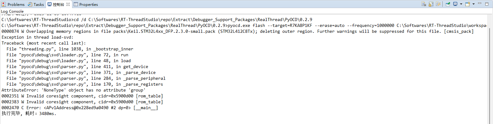
Solution:
Method 1: Use RFP to initialize the device and flash a single-core project.
Method 2: A community developer shared an article about updating the debugger firmware, which supports flashing dual-core projects: https://club.rt-thread.org/ask/article/3387ad4472d12ead.html
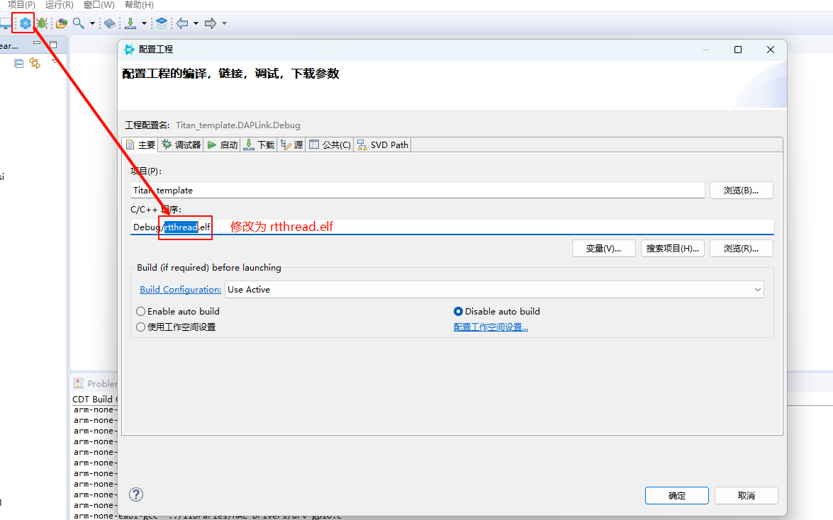
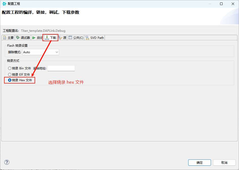
Q8. Error “rtthread.bin not found (file not found)” when flashing
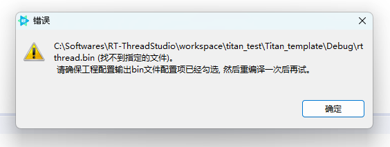
Solution:
Configure the project’s debug and download parameters as shown below:
2. Camera and Display Connection
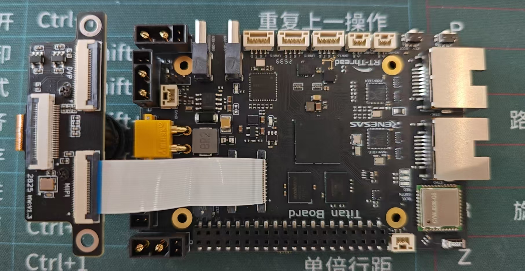
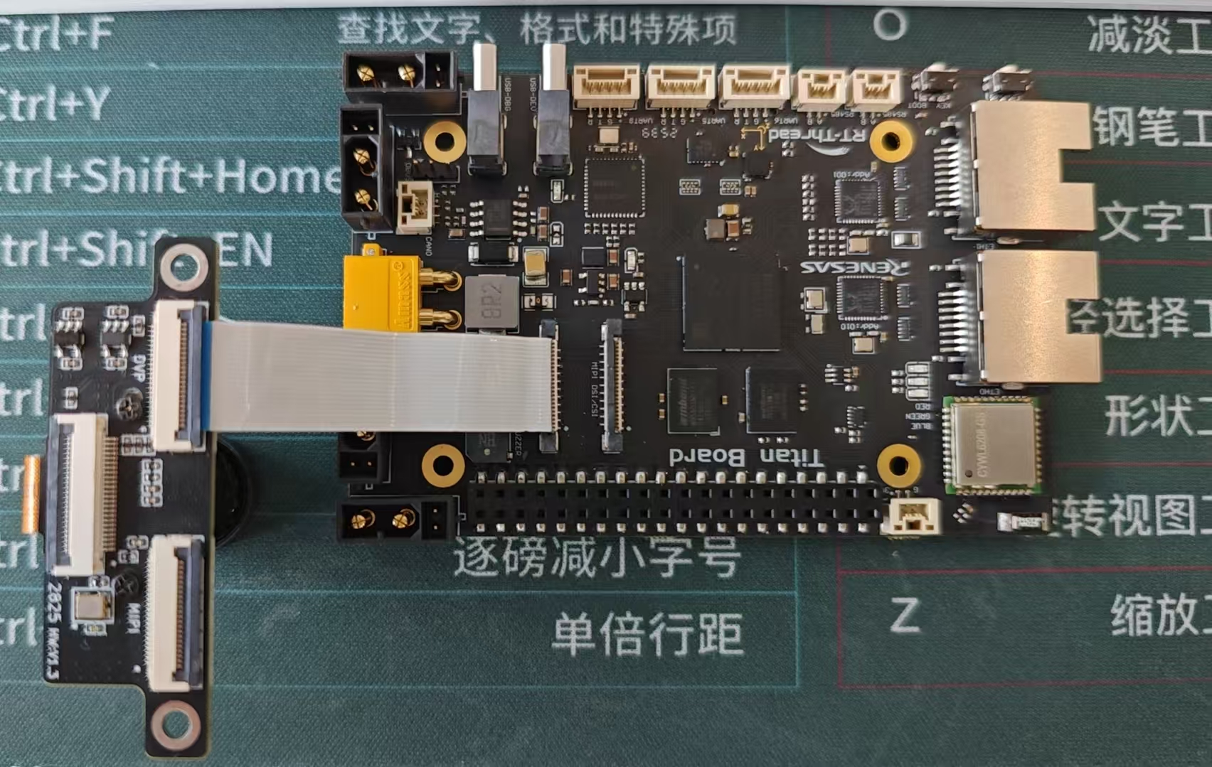
Q9. Camera Connection
Solution:
MIPI CSI:
Use a 22-pin reverse FFC cable to connect the development board’s MIPI DSI/CSI connector to the camera adapter board’s MIPI connector.
CEU:
Use a 22-pin reverse FFC cable to connect the development board’s CEU_CAM connector to the camera adapter board’s DVP connector.
Q10. RGB LCD Connection
Solution:
Display model: ALIENTEK 4.3” RGB LCD 800×480
Use a 40-pin same-direction FFC cable to connect the development board’s LCD_RGB connector to the display.

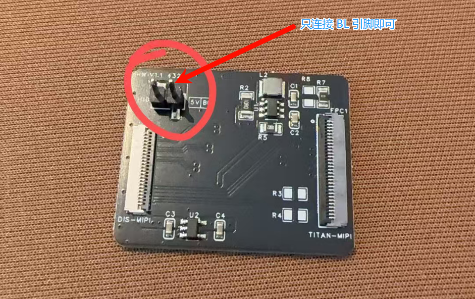
Q11. MIPI LCD Connection
Solution:
Display model: Guanxian TL043WVV02CT
Use a 22-pin reverse FFC cable to connect the development board’s MIPI DSI/CSI connector to the display adapter board’s DIS-MIPI connector. Then connect the MIPI display to the adapter board’s TITAN-MIPI connector.
A Dupont wire is required to connect the BL pin on the display adapter board to the PB07 pin (the GPIO pin used to provide backlight can be changed as needed).

3. Runtime Issues
Q12. System freezes after running for a while
Solution:
Possible causes include:
Insufficient task stack space → Increase stack size when creating threads.
Memory leaks → Check heap usage.
Deadlock or priority inversion → Review mutex and semaphore usage.
##Feedback & Support
If you encounter other issues, you can get help through the following channels:
📘 View project documentation: User Manual
🐞 Submit an issue: GitHub Issues
💬 Contact technical support: RT-Thread Community Forum