WDT Usage Instructions
English | Chinese
Introduction
The Watchdog Timer (WDT) ensures that our code runs as expected and can effectively prevent the program from “running away” due to uncontrollable factors. This example demonstrates how to use the WDT module of the RA8 series MCU on the Titan Board, together with the RT-Thread WDT driver framework, to implement watchdog functionality, including timer configuration, feeding the watchdog, and handling timeouts.
WDT (Watchdog Timer) Instruction
1. General Description
The WDT (Watchdog Timer) is a hardware timer used in embedded systems to monitor system operation and prevent the program from hanging or stalling.
If the MCU or processor does not reset (Kick/Reload) the WDT within the specified period, the WDT will automatically reset the system, ensuring it can resume normal operation.
Typical use cases for WDT:
Preventing software infinite loops or task stalls
Improving system reliability and stability
Critical applications such as industrial control, automotive electronics, drones, and communication devices
2. Working Principle
Counter Mode
The WDT includes a decrementing counter that starts from an initial value.
The MCU must reset the counter (Reload/Kick) before it reaches zero.
If the counter reaches zero, a system reset or interrupt is triggered.
Feeding the Watchdog
The MCU periodically writes a specific value to reset the counter.
Commonly called “feeding the dog,” this ensures that during normal operation, the WDT does not reset the system.
Reset/Interrupt Mode
Reset Mode: The WDT expiration directly resets the MCU.
Interrupt Mode: The WDT expiration generates an interrupt, allowing software to attempt recovery first.
3. Types of WDT
Type |
Description |
|---|---|
Independent WDT (IWDT) |
Has its own clock source; continues running during reset or suspend |
Window WDT (WWDT) |
Requires feeding within a specific time window |
Super WDT |
Offers higher precision or longer configurable periods |
Software WDT |
Implemented via software timers, maintained by OS or applications |
4. Key Parameters
Counter width: Determines maximum timeout period
Timeout: Time from last feed to system reset trigger
Clock source: Independent low-speed oscillator or system clock
Reset method: Hardware reset or interrupt notification
Example:
WDT timeout = 500 ms
MCU feeds the WDT every 100 ms
If the MCU stalls and fails to feed the WDT for 500 ms → WDT resets the system
5. Usage Guidelines
Feed periodically: Ensure WDT is refreshed during normal operation.
Feed in critical tasks: Typically in the main loop or key tasks.
Interrupt-safe: Feeding should not be blocked by interrupts.
Reasonable timeout: Must be longer than task execution time but not excessively long.
RA8 Series WDT Module (r_wdt) Instruction
The RA8 MCU series integrates a high-performance WDT module (r_wdt), providing reliable system monitoring with support for both reset and interrupt modes.
1. Key Features
Timer mode: Single-shot or periodic
Clock sources: Low-power oscillator (LPO) or system clock
Reset and interrupt outputs:
Timeout can reset the MCU
Interrupt mode available for software recovery
Counter range: 8–32 bits, configurable timeout period
Safety features:
Protection against unintended writes (unlock sequences required)
Multi-level reset modes (WDT reset, NMI reset)
Independent operation: Runs even in low-power or sleep mode
2. Module Architecture
The RA8 WDT module contains:
Counter Unit – decrements with clock input, detects overflow
Control Registers – configure timeout, mode, and feeding sequence
Status Registers – indicate WDT state, timeout flags, interrupt/reset flags
Reset & Interrupt Unit – triggers MCU reset or interrupt/NMI upon timeout
3. Working Flow
Start WDT: Configure clock source, counter, and timeout period, then enable.
Feed operation: Software writes the specific sequence to reset the counter.
Timeout event: If feeding is missed → counter overflows:
Triggers MCU reset (reset mode)
Triggers interrupt (interrupt mode)
Safety protection: Registers require unlock before modification.
RT-Thread WDT Framework Instruction
RT-Thread WDT (Watchdog Timer) Framework is a unified interface provided by the RT-Thread device driver layer for managing hardware watchdog modules across different MCUs. This framework abstracts the hardware WDT functionality into a standardized device interface, allowing applications to use a consistent API across platforms to implement system self-recovery mechanisms.
1. Device Model
In RT-Thread, the WDT is managed as a device object (a subclass of struct rt_device, with type RT_Device_Class_WDT).
Developers don’t need to deal with low-level hardware register operations — all watchdog functionalities can be implemented through the standard RT-Thread device interfaces.
2. Operation Interfaces
Applications access the watchdog hardware using RT-Thread’s I/O device management interfaces as shown below:
Find the Watchdog Device
rt_device_t rt_device_find(const char* name);
Initialize the Watchdog
rt_err_t rt_device_init(rt_device_t dev);
Control the Watchdog
rt_err_t rt_device_control(rt_device_t dev, rt_uint8_t cmd, void* arg);
Available watchdog control commands are defined as follows:
#define RT_DEVICE_CTRL_WDT_GET_TIMEOUT    (1) /* Get the timeout period */
#define RT_DEVICE_CTRL_WDT_SET_TIMEOUT    (2) /* Set the timeout period */
#define RT_DEVICE_CTRL_WDT_GET_TIMELEFT   (3) /* Get the remaining time before reset */
#define RT_DEVICE_CTRL_WDT_KEEPALIVE      (4) /* Feed the watchdog */
#define RT_DEVICE_CTRL_WDT_START          (5) /* Start the watchdog */
#define RT_DEVICE_CTRL_WDT_STOP           (6) /* Stop the watchdog */
Close the Watchdog Device
rt_err_t rt_device_close(rt_device_t dev);
3. Framework Features
Unified Device Abstraction: All hardware WDTs are exposed to upper layers through the same device interface.
Cross-Platform Support: Applications can be ported across MCU platforms without changing WDT-related code.
Timeout Protection: Supports configurable timeout periods; if the system fails to feed the watchdog, it triggers an interrupt or reset.
Flexible Operating Modes: Supports both interrupt mode and reset mode to meet various application requirements.
High Reliability: Ensures system safety by using hardware-enforced reset mechanisms to recover from system hangs.
Reference: RT-Thread WATCHDOG Device
Hardware Description
None
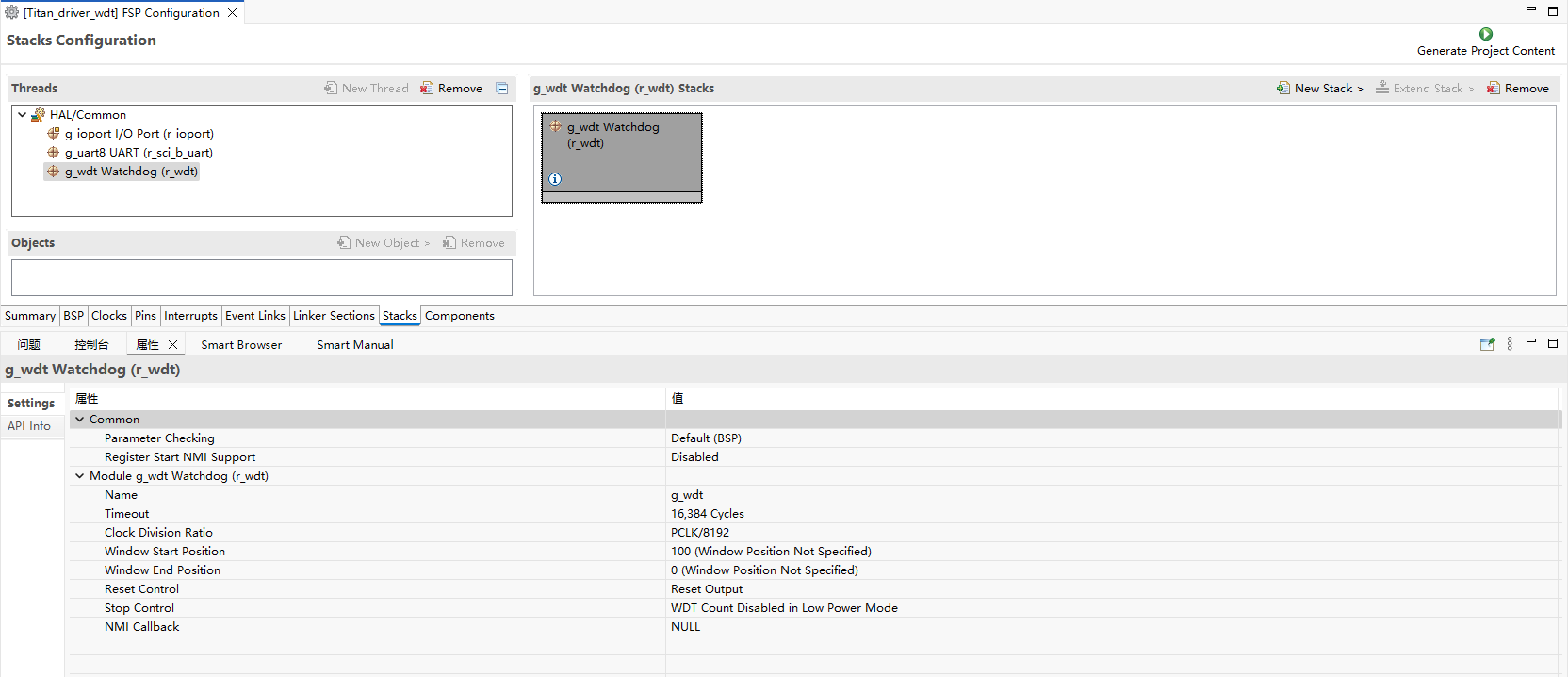
FSP Configuration
Open the FSP tool and create a new stack, selecting
r_wdt.
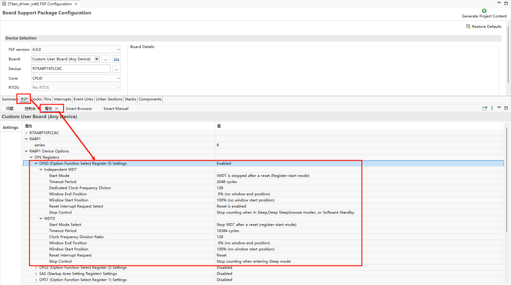
Note: Using WDT requires the
OFS0register configuration to be enabled.
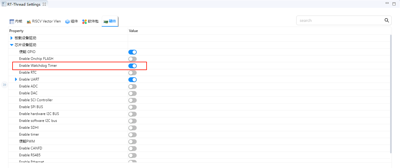
RT-Thread Settings Configuration
Enable WDT.
Example project description
The sample program is located at project/Titan_driver_wdt/src/hal_entry.c.
#include <rtthread.h>
#include "hal_data.h"
#include <rtdevice.h>
#include <board.h>

#define DBG_TAG "wdt"
#define DBG_LVL DBG_LOG
#include <rtdbg.h>

#define WDT_DEVICE_NAME "wdt"    // Default watchdog device name, depending on the BSP
#define WDT_FEED_INTERVAL 1000   // Feeding interval (unit: ms)
#define WDT_TIMEOUT 3            // Watchdog timeout period (unit: s)

static rt_device_t wdt_dev = RT_NULL;
static rt_thread_t feed_thread = RT_NULL;

#define LED_PIN_0    BSP_IO_PORT_06_PIN_00 /* Onboard LED pins */

void hal_entry(void)
{
    rt_kprintf("\nHello RT-Thread!\n");
    rt_kprintf("==================================================\n");
    rt_kprintf("This example project is an driver wdt routine!\n");
    rt_kprintf("==================================================\n");

    LOG_I("Tips:");
    LOG_I("You can run wdt testcase by executing the instruction: \'wdt_sample\'");

    while (1)
    {
        rt_pin_write(LED_PIN_0, PIN_HIGH);
        rt_thread_mdelay(1000);
        rt_pin_write(LED_PIN_0, PIN_LOW);
        rt_thread_mdelay(1000);
    }
}

static void feed_dog_entry(void *parameter)
{
    int count = 0;

    while (1)
    {
        if (count < 10)
        {
            rt_device_control(wdt_dev, RT_DEVICE_CTRL_WDT_KEEPALIVE, RT_NULL);
            LOG_I("[FeedDog] Feeding watchdog... %d", count);
        }
        else
        {
            LOG_E("[FeedDog] Simulate exception! Stop feeding.");
        }

        count++;
        rt_thread_mdelay(WDT_FEED_INTERVAL);
    }
}

static int wdt_sample(void)
{
    rt_err_t ret;

    wdt_dev = rt_device_find(WDT_DEVICE_NAME);
    if (wdt_dev == RT_NULL)
    {
        LOG_E("Cannot find %s device!", WDT_DEVICE_NAME);
        return -1;
    }

    ret = rt_device_control(wdt_dev, RT_DEVICE_CTRL_WDT_START, RT_NULL);
    if (ret != RT_EOK)
    {
        LOG_E("Start watchdog failed!");
        return -1;
    }

    LOG_I("Watchdog started...", WDT_TIMEOUT);

    feed_thread = rt_thread_create("feed_dog", feed_dog_entry, RT_NULL, 1024, 10, 10);
    if (feed_thread != RT_NULL)
        rt_thread_startup(feed_thread);

    return 0;
}
MSH_CMD_EXPORT(wdt_sample, wdt_sample);
Compilation & Download
RT-Thread Studio: Download the Titan Board resource package in the RT-Thread Studio package manager, then create a new project and compile it.
After compilation, connect the USB-DBG interface of the development board to the PC, and download the firmware to the development board.
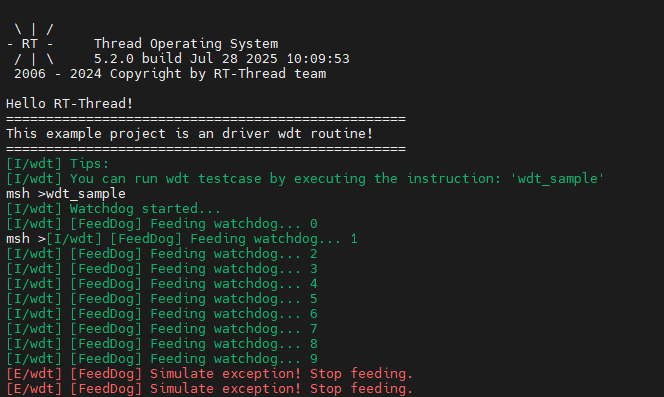
Run Effects
Enter the wdt_sample command at the terminal to run the WDT test program. After feeding the dog 10 times, stop feeding the dog to simulate an abnormal program situation.