Buzzer Usage Instructions
English | Chinese
Introduction
In practical applications, the use of timers is almost always indispensable. This example demonstrates how to use the GPT (General Purpose Timer) on the Titan Board to generate PWM signals and drive a passive buzzer to play a melody.
The selected melody in this example is the classic children’s song “Two Tigers”. By dynamically adjusting the PWM frequency through the timer, the buzzer produces different musical notes.
Through this example, users will learn:
How to configure the RA8 GPT module and generate PWM output
How to use the PWM device driver framework under RT-Thread
How to synthesize different tones using PWM duty cycle and frequency, and thereby implement simple music playback
Introduction to PWM / GPT
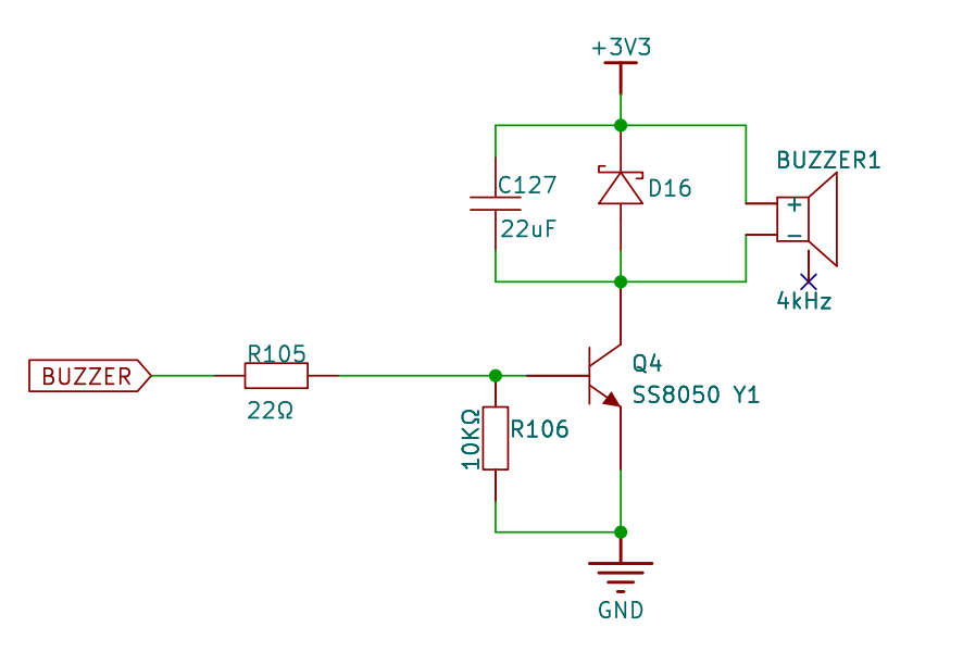
Passive Buzzer and PWM
A passive buzzer is essentially a small piezoelectric or electromagnetic transducer that requires an external AC signal (square wave) at a certain frequency to produce sound.
The pitch is determined by the PWM frequency, while the loudness/timbre is mainly influenced by the duty cycle and driving capability. A 50% duty cycle is commonly used to produce a pure tone with the strongest fundamental frequency and minimal harmonics.
If the buzzer has a high rated current (or the onboard GPIO cannot drive it directly), it is recommended to use an NPN/MOSFET low-side switch + diode (for electromagnetic types) for protection. Piezoelectric buzzers generally do not require a freewheeling diode but adding a 100–1kΩ resistor in series is still recommended to limit current and reduce noise (depending on the specific device and board).
Basic Concepts of PWM
Period (T): The total time of one high-low cycle.
Frequency (f):
f = 1 / T(in Hz).Duty Cycle (D): The ratio of high-level duration to the total period,
D = t_high / T.Voltage Level: Usually VCC (e.g., 3.3V).
When using PWM to play music on a buzzer:
Changing frequency f → changes the pitch.
Changing duration → changes the beat and rhythm.
Fine-tuning duty cycle D (typically 40–60%) → affects loudness and timbre.
Overview of RA8 GPT (for PWM)
GPT (General PWM Timer): A general-purpose timer in the RA8 series that supports PWM output, typically with A/B channels (as mapped by FSP/BSP pins).
Typical features: configurable count source/divider, period/compare value, edge-aligned/center-aligned modes, and support for complementary output with dead time (often used for motors/drivers).
Under RT-Thread, GPT can be controlled via the PWM device driver: simply set the period and pulse width to generate PWM.
Setting Frequency and Duty Cycle in RT-Thread
rt_pwm_set(device, channel, period_ns, pulse_ns) uses nanoseconds:
Period (ns):
T_ns = 10^9 / fHigh-level duration (ns):
t_high = T_ns * D
For example, with D = 50%, t_high = T_ns / 2.
Note:
period_nsandpulse_nsare usually 32-bit values. Avoid extremely low frequencies that result in very large periods; for very low frequencies, consider software timers or segmented playback.
Reference: RT-Thread PWM Device
Hardware Description
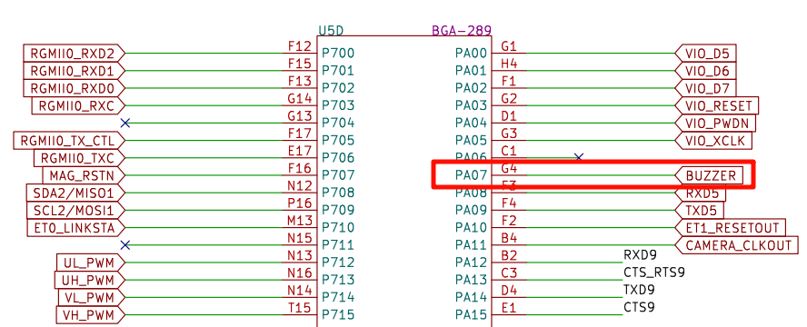
The pin of the buzzer is PA07.
FSP Configuration
The FSP is configured to enable GPT7 as a PWM mode:
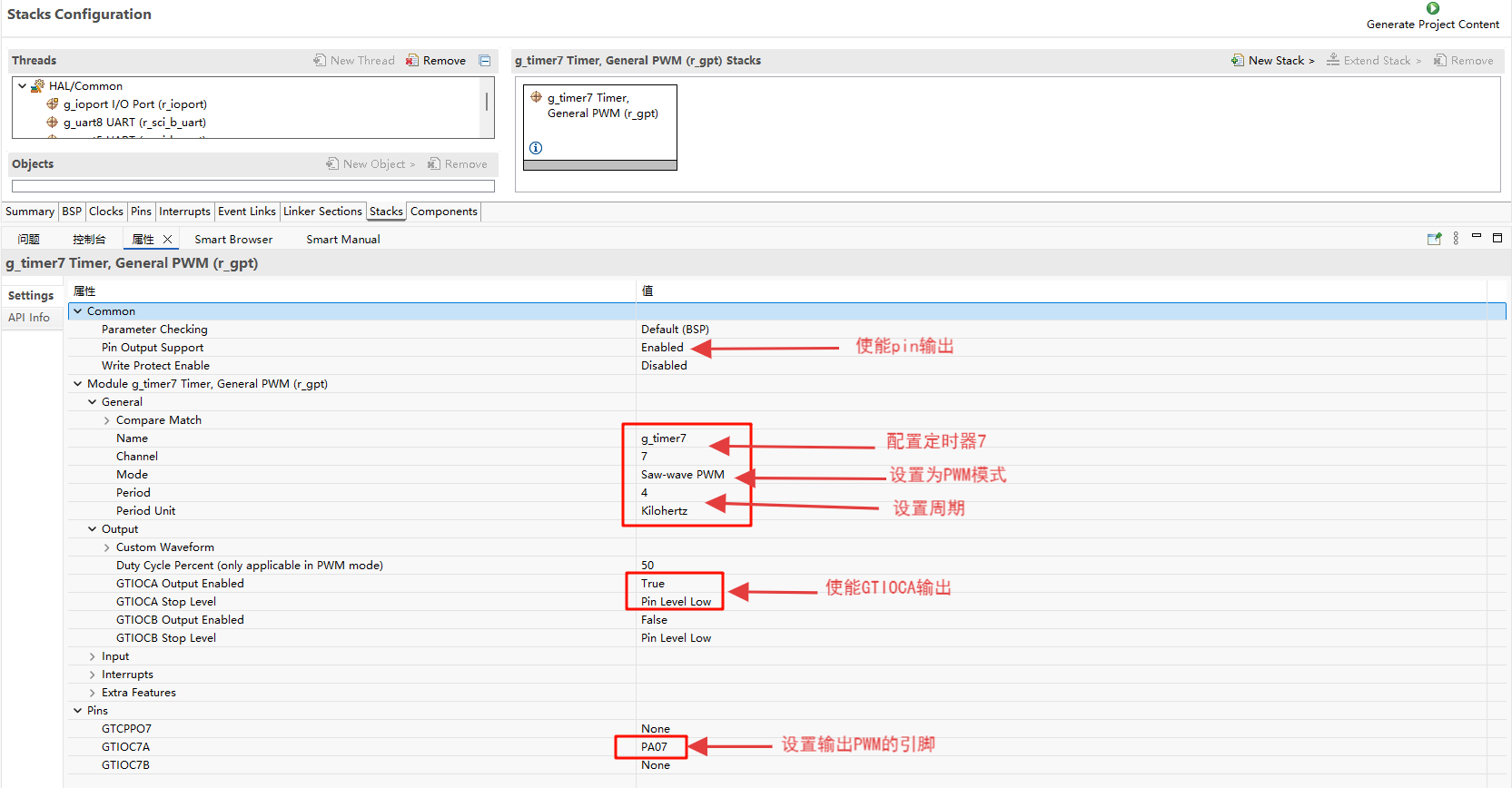
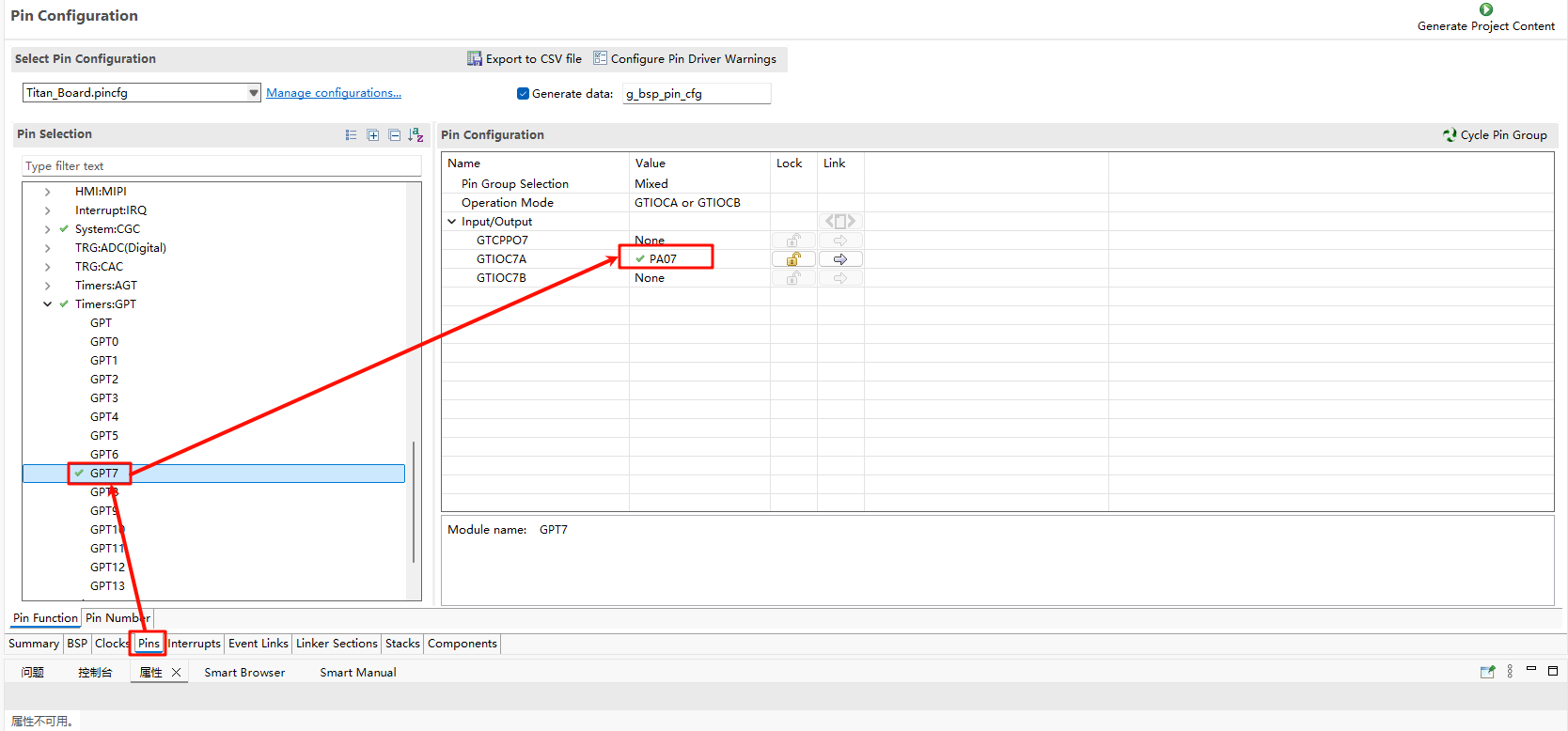
Additionally, the pins for GPT7 are enabled:
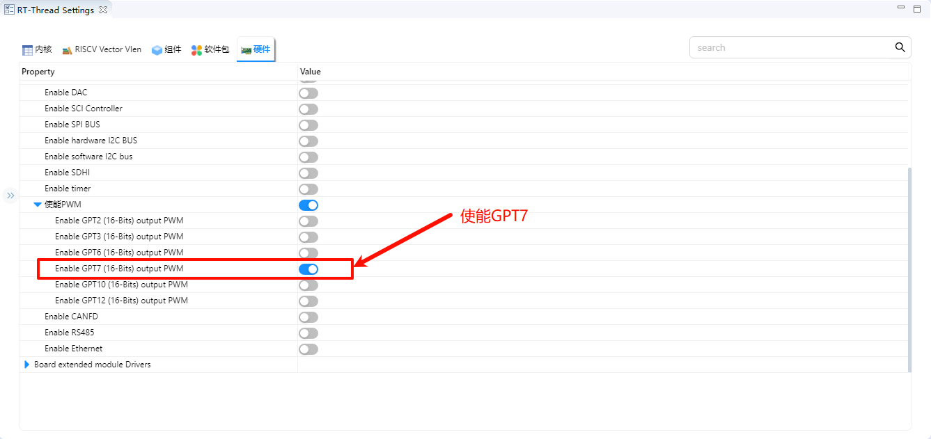
RT-Thread Settings Configuration
In the configuration, enable PWM7:
Example Project Instructions
To play “Two Tigers”, we need to define the frequencies corresponding to the numbered musical notation (unit: Hz):
Note |
Frequency (Hz) |
|---|---|
C4 |
262 |
D4 |
294 |
E4 |
330 |
F4 |
349 |
G4 |
392 |
A4 |
440 |
B4 |
494 |
C5 |
523 |
The actual output frequency may be affected by GPT clock/divider/count step quantization. The driver will select the nearest achievable value within the range. For more accurate pitch, it’s recommended to choose frequencies with smaller quantization errors first (or adjust the system clock/divider).
The source code for this example is located in /project/Titan_basic_buzzer/src/buzzer.c:
#include <rtthread.h>
#include <rtdevice.h>

#define PWM_DEV_NAME        "pwm7"  /* PWM Device Name */
#define PWM_DEV_CHANNEL     0       /* PWM Channel */

struct rt_device_pwm *pwm_dev;

typedef struct
{
    uint16_t freq;   // Frequency (Hz)
    uint16_t duration; // Duration (ms)
} note_t;

note_t song[] =
{
    {262,400}, {294,400}, {330,400}, {262,400},  // 1 2 3 1
    {262,400}, {294,400}, {330,400}, {262,400},  // 1 2 3 1
    {330,400}, {349,400}, {392,800},             // 3 4 5
    {330,400}, {349,400}, {392,800},             // 3 4 5
    {392,200}, {440,200}, {392,200}, {349,200}, {330,400}, {262,400}, // 5 6 5 4 3 1
    {392,200}, {440,200}, {392,200}, {349,200}, {330,400}, {262,400}, // 5 6 5 4 3 1
    {262,400}, {196,400}, {262,400}, {0,400},    // 1(低) 7(低) 1 高 休止
    {262,400}, {196,400}, {262,400}, {0,400},    // 1 7 1 休止
};

static int buzzer_test(void)
{
    pwm_dev = (struct rt_device_pwm *)rt_device_find(PWM_DEV_NAME);
    if (!pwm_dev)
    {
        rt_kprintf("Cannot find PWM device %s\n", PWM_DEV_NAME);
        return -1;
    }

    for (size_t i = 0; i < sizeof(song)/sizeof(song[0]); i++)
    {
        if (song[i].freq == 0)
        {
            rt_pwm_disable(pwm_dev, PWM_DEV_CHANNEL);
        }
        else
        {
            uint32_t period_ns = 1000000000 / song[i].freq;  // ns
            uint32_t pulse_ns  = period_ns / 2;              // 50%

            rt_pwm_set(pwm_dev, PWM_DEV_CHANNEL, period_ns, pulse_ns);
            rt_pwm_enable(pwm_dev, PWM_DEV_CHANNEL);
        }

        rt_thread_mdelay(song[i].duration);
    }

    rt_pwm_disable(pwm_dev, PWM_DEV_CHANNEL);
    return 0;
}
MSH_CMD_EXPORT(buzzer_test, Play song on buzzer);
Compilation & Download
RT-Thread Studio: Download the Titan Board resource package in the RT-Thread Studio package manager, then create a new project and compile it.
After compilation, connect the development board’s USB-DBG interface to the PC, and download the firmware to the development board.
Running Results
Type buzzer_sample in the serial terminal to see the effect. The buzzer will play “Two Tigers”.