RGB LCD 示例说明
中文 | English
简介
本示例演示了如何在 Titan Board 上使用 RA8 系列 MCU 的 GLCDC 模块结合 RT-Thread 的 LCD 驱动框架驱动 RGB LCD 屏幕,实现图像显示与界面更新。文档将详细介绍 RA8 系列 GLCDC 外设特性及 RT-Thread LCD 驱动框架,并提供示例配置和操作方法。
RA8 系列 GLCDC 模块
1. 简介
**GLCDC(Graphics LCD Controller)**是 RA8 系列 MCU 内置的高性能图形控制器模块,专门用于驱动 TFT/RGB LCD 屏幕,支持各种分辨率、色彩格式和图像处理功能。结合 RT-Thread 的 LCD 驱动框架,可以实现统一接口下的屏幕初始化、刷新、图像绘制及 DMA 加速等功能。
RA8 系列 GLCDC (Graphics LCD Controller) 提供了从 MCU 内部存储器或外部图像缓存向 RGB/LCD 显示屏输出图像的能力。它集成了:
帧缓冲控制:可配置多帧缓冲,实现页面切换或双缓冲显示
颜色格式支持:RGB565, RGB888, ARGB8888 等
图形处理功能:背景图层、文字/图形合成、透明度混合、调色板等
同步信号生成:HSYNC, VSYNC, DE(Data Enable)等
DMA 支持:高速数据传输,减少 CPU 占用
中断功能:帧结束中断、行结束中断等
2. 模块架构
RA8 GLCDC 模块主要包含以下子模块:
图层合成单元(Layer Composition Unit)
支持多图层叠加
提供 alpha blending、透明度控制、颜色键控
可以对图层进行旋转、翻转处理
帧缓冲接口(Frame Buffer Interface)
支持访问 MCU 内部 SRAM 或外部存储器
提供单/双缓冲模式,保证连续显示
配合 DMA 自动读取图像数据
DMA 控制器(DMA Controller)
自动传输像素数据到 RGB 输出端口
可配置突发长度,提高带宽利用率
支持循环传输,适合视频或动画场景
同步信号生成器(Timing Generator)
自动生成 HSYNC/VSYNC/DE 信号
支持 TTL 接口 RGB 时序
可配置极性、同步宽度、前后肩时间等
中断与事件处理单元(Interrupt/Event Controller)
提供帧结束中断、行结束中断
可用于页面切换、动态绘制或滚动显示
支持 DMA 传输完成触发中断
3. GLCDC 工作原理
帧缓冲读取
GLCDC 通过 DMA 从内存读取图像数据,支持单/双缓冲模式,保证连续显示。
图层合成
支持多图层叠加,例如背景图层 + 前景图层 + 图标/文字图层
提供透明度控制和调色板映射
像素时序输出
根据 LCD 的接口要求生成 HSYNC/VSYNC/DE 信号
支持 RGB 并行接口、TTL 接口或 LVDS(视具体板级实现)
中断与事件
帧结束中断(VBlank):可用于更新下一帧数据
行结束中断:可用于滚动显示或动态绘制
4. GLCDC 支持的功能与特性
功能类别 |
描述 |
|---|---|
分辨率 |
最高可达 800×480 (具体取决于 MCU 型号及时钟配置) |
色彩模式 |
RGB565、RGB888、ARGB8888 等 |
多图层 |
背景 + 前景 + 符号图层,可叠加混合 |
帧缓冲 |
支持单帧/双帧缓冲模式,DMA 传输提高性能 |
调色板 |
支持 8/16 位调色板映射,实现色彩转换 |
同步信号 |
HSYNC, VSYNC, DE,可配置极性和时序 |
DMA 支持 |
自动从内存传输图像数据,无需 CPU 干预 |
中断 |
帧结束、行结束中断,可用于屏幕刷新同步 |
旋转/翻转 |
支持 90°/180°/270°旋转及 X/Y 翻转 |
RT-Thread LCD 驱动框架
RT-Thread 提供了 统一的 LCD 驱动框架,通过封装底层控制器,支持不同屏幕类型与 MCU 外设。框架主要接口如下:
主要接口
函数/宏 |
功能 |
|---|---|
|
查找 LCD 设备句柄 |
|
打开设备,初始化 LCD 硬件 |
|
控制 LCD,例如更新lcd图像、设置背光、读取屏幕信息 |
|
向 LCD 写入像素数据 |
|
从 LCD 读取像素数据(部分屏幕支持) |
|
关闭设备 |
硬件说明
FSP 配置
HyperRAM 配置
新建 r_ospi_b stack:
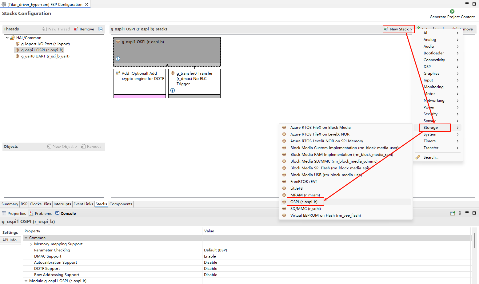
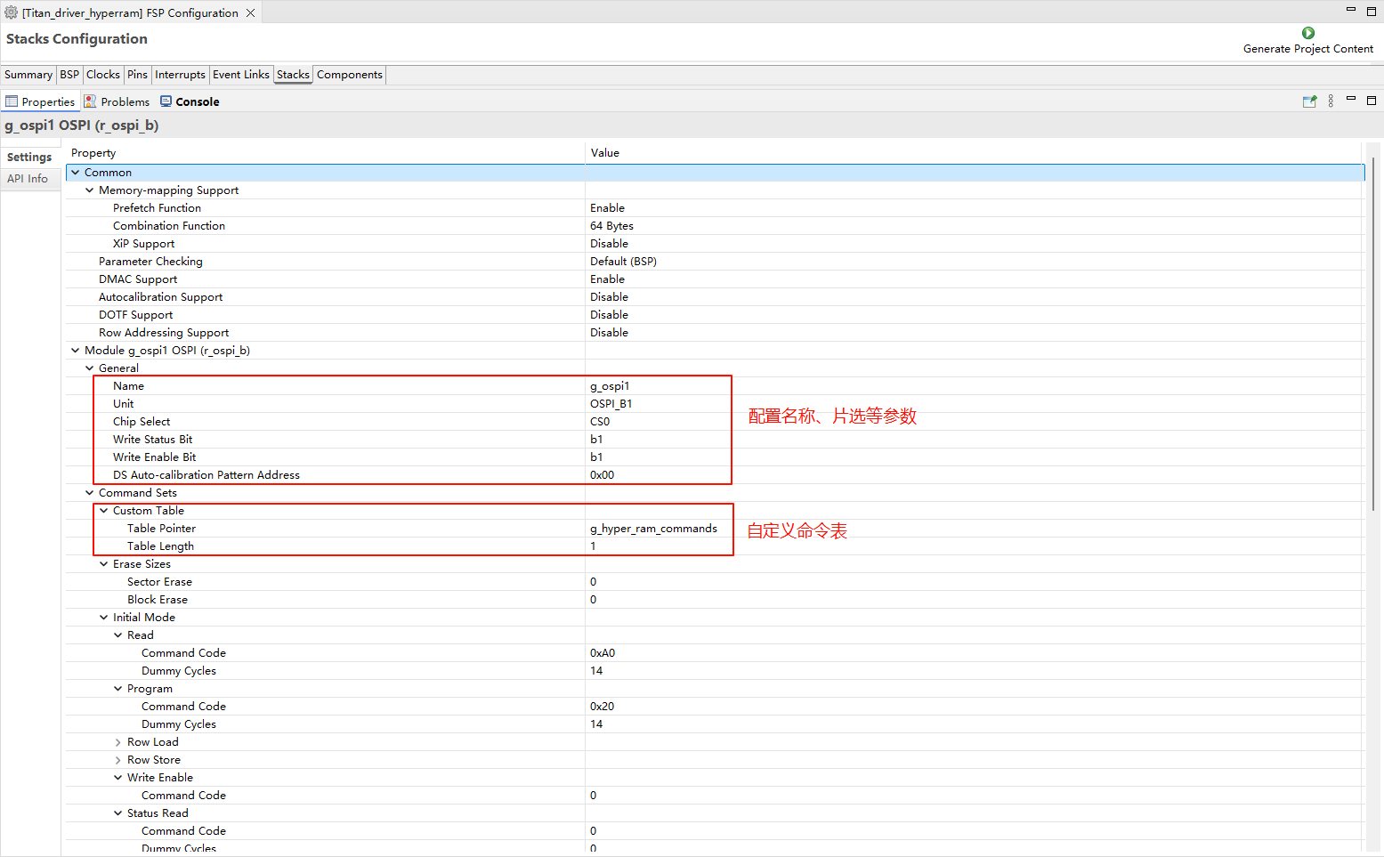
配置 r_ospi_b stack:
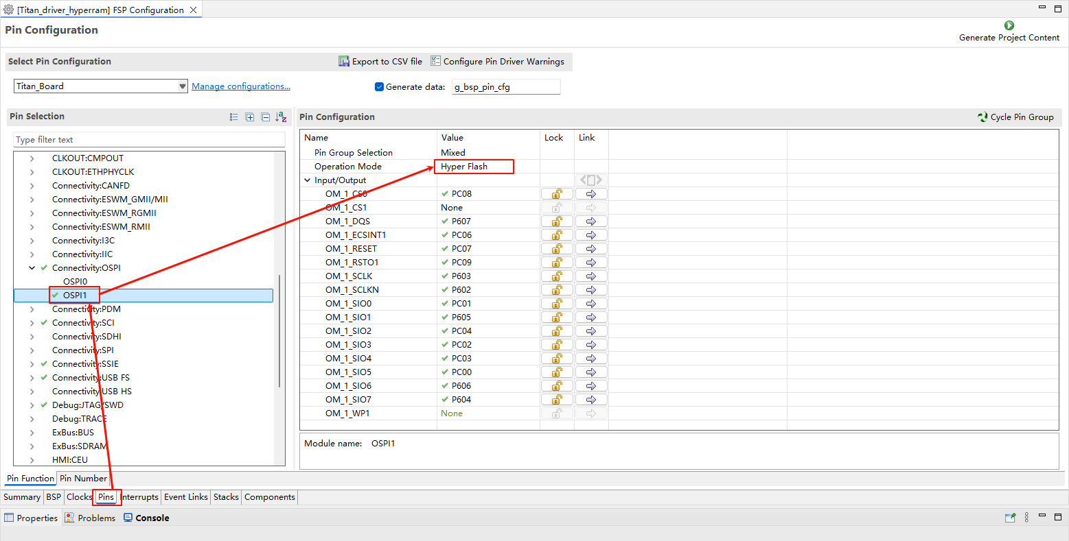
HyperRAM 引脚配置:
RGB LCD 配置
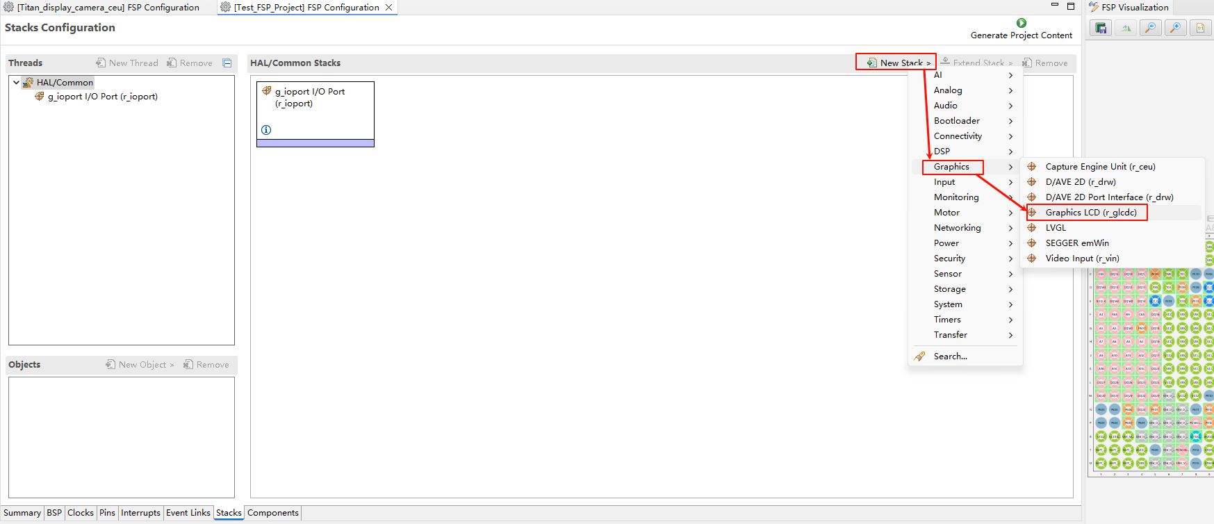
新建
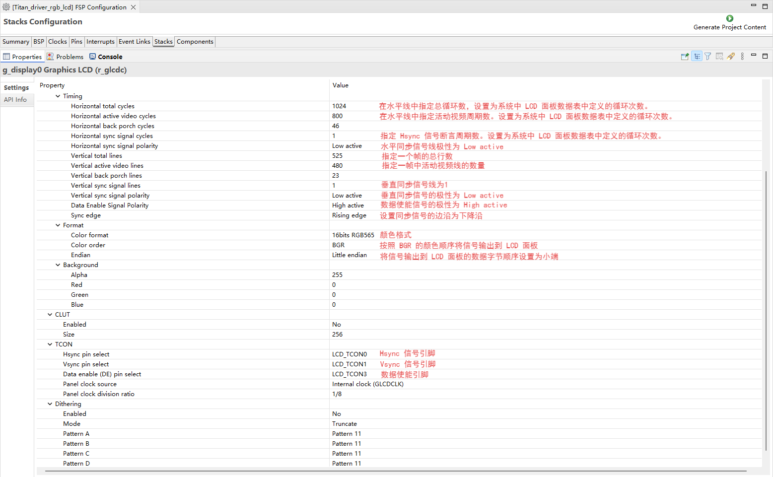
r_glcdcstack:
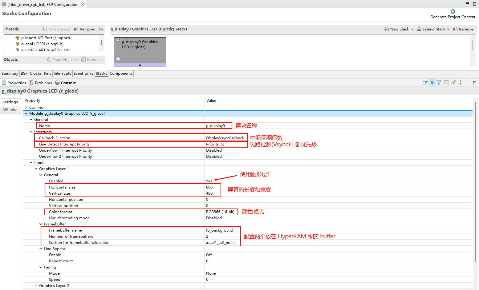
配置中断回调和图形层1:
配置输出参数、CLUT、TCON和抖动。
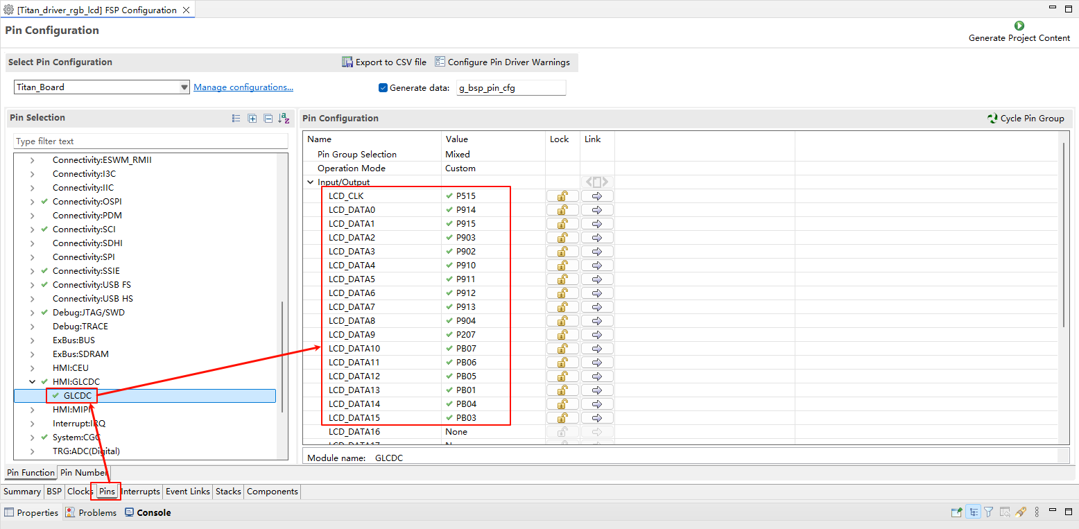
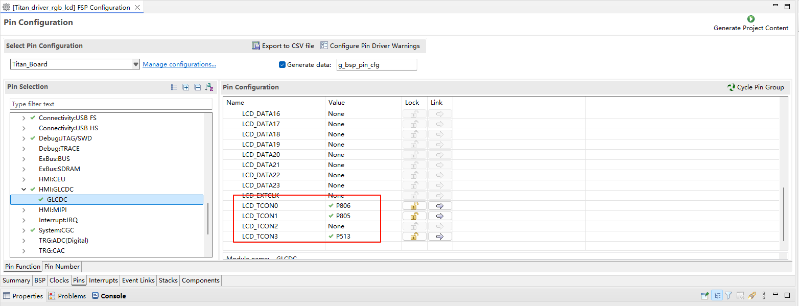
配置 GLCDC 的引脚:
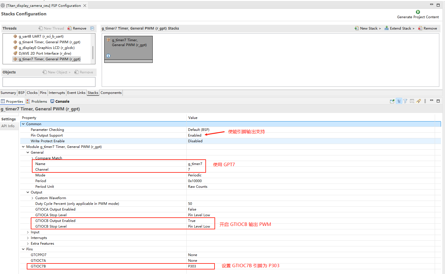
LCD 背光配置
新建
r_gptstack:
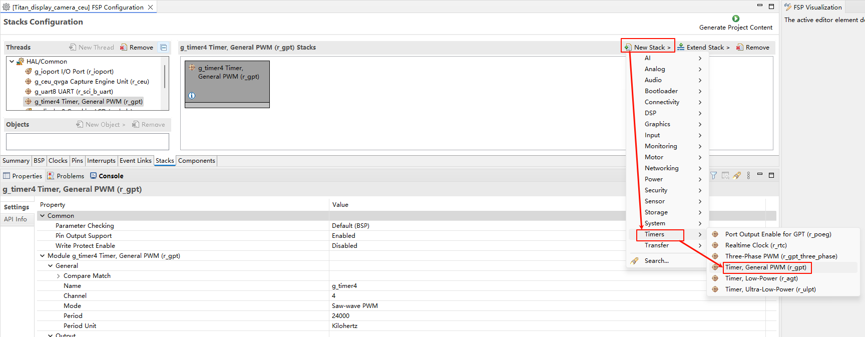
配置背光 PWM 输出:
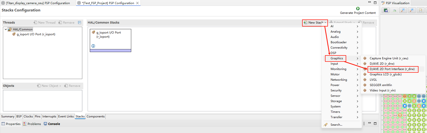
D/AVE 2D 配置
新建
r_drwstack:
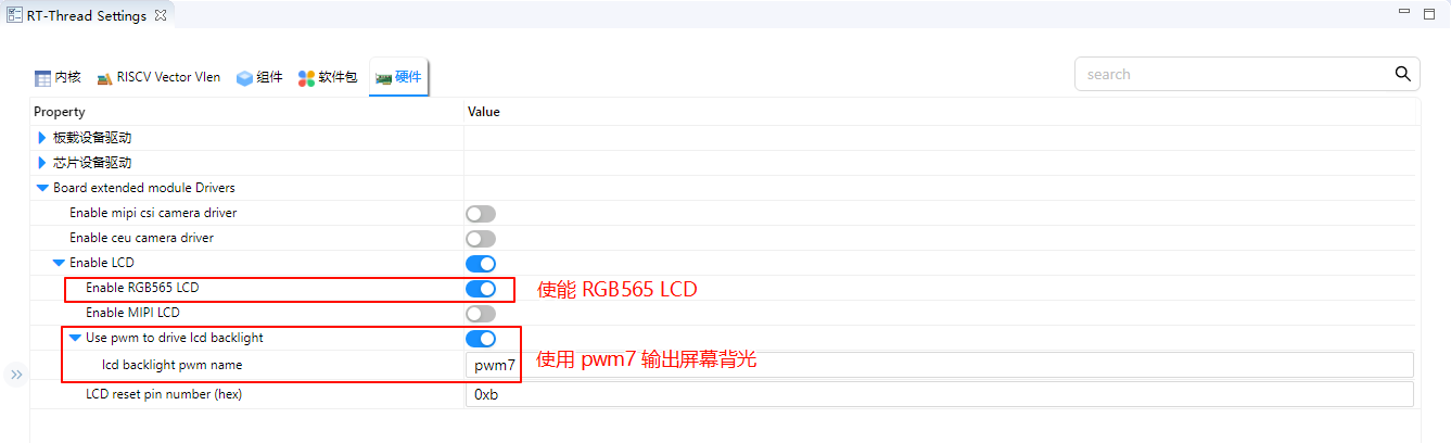
RT-Thread Settings 配置
在 RT-Thread Settings 中使能 RGB565 LCD,使用 pwm7 输出屏幕背光。
编译&下载
RT-Thread Studio:在RT-Thread Studio 的包管理器中下载 Titan Board 资源包,然后创建新工程,执行编译。
编译完成后,将开发板的 USB-DBG 接口与 PC 机连接,然后将固件下载至开发板。
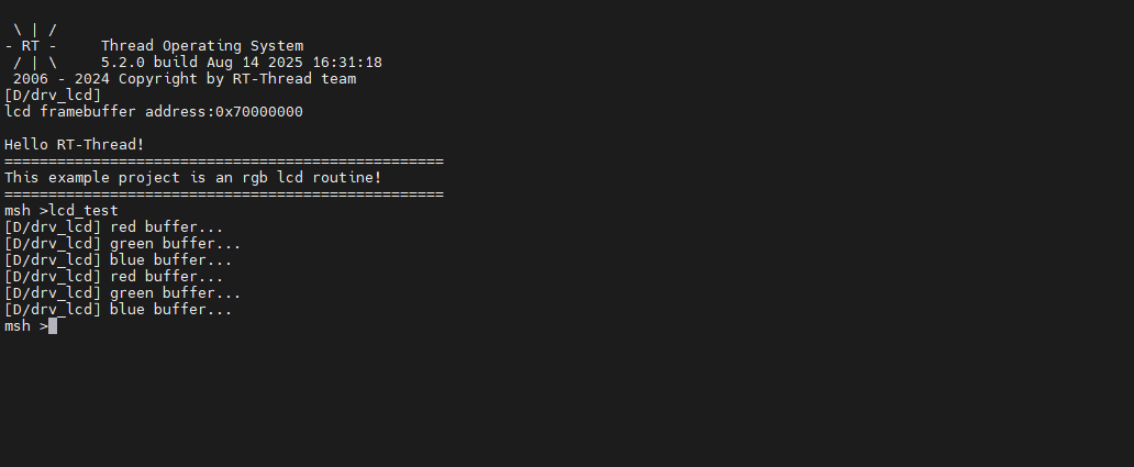
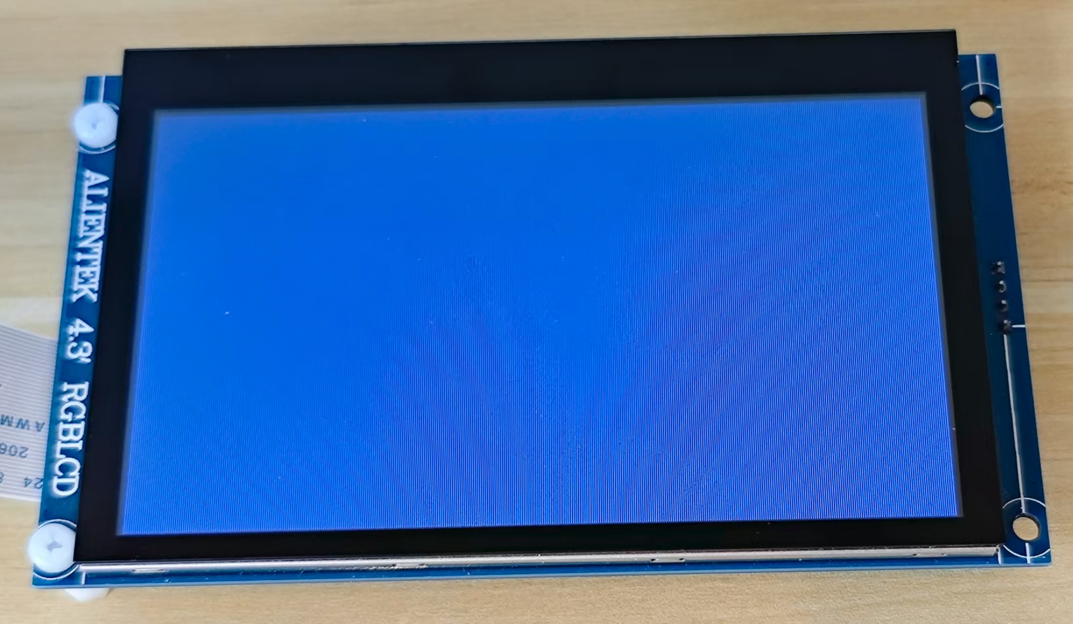
运行效果
复位开发板后在终端输入 lcd_test 命令运行刷屏程序。