IMU 传感器示例说明
中文 | English
简介
本示例展示了如何在 Titan Board Mini 上使用 LSM6DS3TR-C 六轴 IMU 传感器 实现惯性测量功能,通过 I2C 接口读取 3轴加速度计 和 3轴陀螺仪 数据,结合 RT-Thread 传感器框架 实现完整的传感器数据采集和处理。
主要功能包括:
使用 LSM6DS3TR-C 实现 6 轴惯性测量
读取 3 轴加速度计数据 (X/Y/Z)
读取 3 轴陀螺仪数据 (X/Y/Z)
支持多种量程和采样率配置
集成 RT-Thread 传感器框架
硬件介绍
1. LSM6DS3TR-C IMU 传感器
Titan Board Mini 板载 LSM6DS3TR-C 高性能六轴 IMU 传感器:
参数 |
说明 |
|---|---|
型号 |
LSM6DS3TR-C |
制造商 |
STMicroelectronics (意法半导体) |
类型 |
6 轴 IMU (3轴加速度计 + 3轴陀螺仪) |
接口 |
I2C / SPI |
工作电压 |
1.71V - 3.6V |
温度范围 |
-40°C ~ +85°C |
封装 |
2.5mm x 3mm x 0.83mm LGA-14 |
2. 加速度计特性
LSM6DS3TR-C 内置高性能 3 轴加速度计:
量程选择:±2g / ±4g / ±8g / ±16g
分辨率:16-bit ADC
输出数据率:1.6Hz - 6.66kHz
噪声密度:90μg/√Hz
零偏偏差:±40mg
带宽:可配置 (通常 50Hz - 1.6kHz)
3. 陀螺仪特性
LSM6DS3TR-C 内置高精度 3 轴陀螺仪:
量程选择:±125 / ±250 / ±500 / ±1000 / ±2000 dps
分辨率:16-bit ADC
输出数据率:1.6Hz - 6.66kHz
噪声密度:3.8mdps/√Hz
零偏稳定性:±5dps
带宽:可配置
4. 主要功能
高级功能
FIFO 缓存:9KB FIFO,支持多种模式
中断功能:运动唤醒、自由落体、6D方向检测
传感器融合:内置低功耗传感器融合算法
自检功能:支持自检模式
低功耗模式:多种低功耗工作模式
数据处理
硬件滤波:可配置数字滤波器
数据融合:支持加速度计+陀螺仪数据融合
时间戳:内置时间戳功能
轮询/中断:支持轮询和中断数据读取
软件架构
1. 分层设计
IMU 传感器系统采用分层架构:
应用程序层 (用户代码)
    ↓
RT-Thread Sensor Framework - 传感器框架
    ↓
LSM6DS3TR-C Driver - IMU驱动
    ↓
Sensor HAL - 传感器硬件抽象层
    ↓
I2C/SPI Driver - I2C/SPI驱动
    ↓
FSP I2C/SPI HAL - 硬件抽象层
2. 核心组件
移植层接口
需要实现的平台相关接口 (lsm6ds3tr-c_port.c):
/* I2C 读写接口 */
int32_t platform_write(void *handle, uint8_t reg, const uint8_t *bufp, uint16_t len);
int32_t platform_read(void *handle, uint8_t reg, uint8_t *bufp, uint16_t len);

/* 延时接口 */
void platform_delay(uint32_t ms);
RT-Thread 传感器框架
RT-Thread 提供的统一传感器设备接口:
/* 查找传感器设备 */
rt_device_t rt_device_find(const char *name);

/* 打开传感器设备 */
rt_err_t rt_device_open(rt_device_t dev, rt_uint16_t oflags);

/* 读取传感器数据 */
rt_size_t rt_device_read(rt_device_t dev, rt_off_t pos, void *buffer, rt_size_t size);

/* 接收传感器数据 */
rt_err_t rt_device_set_rx_indicate(rt_device_t dev, rt_err_t (*rx_ind)(rt_device_t dev, rt_size_t size));
3. 工程结构
Titan_Mini_peripheral_imu/
├── src/
│   └── hal_entry.c          # 主程序入口
└── packages/
    └── lsm6ds3tr/           # LSM6DS3TR-C 驱动包
        ├── lsm6ds3tr-c_reg.h    # 寄存器定义和驱动接口
        ├── lsm6ds3tr-c_reg.c    # 寄存器级驱动实现
        └── lsm6ds3tr-c_port.c   # 平台移植层
使用说明
1. 初始化流程
系统初始化时需要初始化 I2C 接口和 IMU 传感器:
#include <rtthread.h>
#include "lsm6ds3tr-c_reg.h"

/* I2C 配置 */
#define LSM6DS3TR_C_I2C_BUS    "i2c2"
#define LSM6DS3TR_C_I2C_ADDR    0x6A  /* SA0引脚接GND */

void hal_entry(void)
{
    stmdev_ctx_t imu_ctx = {0};

    /* 初始化 I2C 接口 */
    struct rt_i2c_bus_device *i2c_bus = rt_i2c_bus_device_find(LSM6DS3TR_C_I2C_BUS);
    if (i2c_bus == RT_NULL)
    {
        rt_kprintf("I2C bus not found!\n");
        return;
    }

    /* 配置设备读写接口 */
    imu_ctx.handle    = i2c_bus;
    imu_ctx.write_reg = platform_write;
    imu_ctx.read_reg  = platform_read;

    /* 初始化传感器 */
    if (lsm6ds3tr_c_init(&imu_ctx) != LSM6DS3TR_C_OK)
    {
        rt_kprintf("LSM6DS3TR-C initialization failed!\n");
        return;
    }

    /* 配置加速度计 */
    lsm6ds3tr_c_xl_full_scale_set(&imu_ctx, LSM6DS3TR_C_2g);          /* ±2g */
    lsm6ds3tr_c_xl_data_rate_set(&imu_ctx, LSM6DS3TR_C_ODR_104Hz);  /* 104Hz */

    /* 配置陀螺仪 */
    lsm6ds3tr_c_gy_full_scale_set(&imu_ctx, LSM6DS3TR_C_250dps);    /* ±250dps */
    lsm6ds3tr_c_gy_data_rate_set(&imu_ctx, LSM6DS3TR_C_ODR_104Hz);  /* 104Hz */

    rt_kprintf("LSM6DS3TR-C initialized successfully!\n");

    /* 主循环 - 读取传感器数据 */
    while (1)
    {
        /* 读取加速度计数据 */
        lsm6ds3tr_c_axis3bit16_t acc_raw;
        lsm6ds3tr_c_acceleration_raw_get(&imu_ctx, &acc_raw);

        /* 读取陀螺仪数据 */
        lsm6ds3tr_c_axis3bit16_t gyro_raw;
        lsm6ds3tr_c_angular_rate_raw_get(&imu_ctx, &gyro_raw);

        /* 数据转换为物理单位 */
        float acc_x = acc_raw.i16bit[0] / 32768.0f * 2.0f;  /* 2g 量程 */
        float acc_y = acc_raw.i16bit[1] / 32768.0f * 2.0f;
        float acc_z = acc_raw.i16bit[2] / 32768.0f * 2.0f;

        float gyro_x = gyro_raw.i16bit[0] / 32768.0f * 250.0f;  /* 250dps 量程 */
        float gyro_y = gyro_raw.i16bit[1] / 32768.0f * 250.0f;
        float gyro_z = gyro_raw.i16bit[2] / 32768.0f * 250.0f;

        /* 打印数据 */
        rt_kprintf("ACC: X=%.3fg Y=%.3fg Z=%.3fg | GYRO: X=%.2fdps Y=%.2fdps Z=%.2fdps\n",
                   acc_x, acc_y, acc_z, gyro_x, gyro_y, gyro_z);

        rt_thread_mdelay(100);  /* 10Hz 读取频率 */
    }
}
2. I2C 平台接口实现
移植层需要实现 I2C 读写函数:
#include <rtthread.h>
#include <rtdevice.h>
/* I2C 写入 */
int32_t platform_write(void *handle, uint8_t reg, const uint8_t *bufp, uint16_t len)
{
struct rt_i2c_bus_device *i2c_bus = (struct rt_i2c_bus_device *)handle;
struct rt_i2c_msg msgs[2];
/* 写寄存器地址 */
msgs[0].addr = LSM6DS3TR_C_I2C_ADDR;
msgs[0].flags = RT_I2C_WR;
msgs[0].buf = ®
msgs[0].len = 1;
/* 写数据 */
msgs[1].addr = LSM6DS3TR_C_I2C_ADDR;
msgs[1].flags = RT_I2C_WR | RT_I2C_NO_START;
msgs[1].buf = (uint8_t *)bufp;
msgs[1].len = len;
if (rt_i2c_transfer(i2c_bus, msgs, 2) != 2)
{
return -1;
}
return 0;
}
/* I2C 读取 */
int32_t platform_read(void *handle, uint8_t reg, uint8_t *bufp, uint16_t len)
{
struct rt_i2c_bus_device *i2c_bus = (struct rt_i2c_bus_device *)handle;
struct rt_i2c_msg msgs[2];
/* 写寄存器地址 */
msgs[0].addr = LSM6DS3TR_C_I2C_ADDR;
msgs[0].flags = RT_I2C_WR;
msgs[0].buf = ®
msgs[0].len = 1;
/* 读数据 */
msgs[1].addr = LSM6DS3TR_C_I2C_ADDR;
msgs[1].flags = RT_I2C_RD;
msgs[1].buf = bufp;
msgs[1].len = len;
if (rt_i2c_transfer(i2c_bus, msgs, 2) != 2)
{
return -1;
}
return 0;
}
/* 延时函数 */
void platform_delay(uint32_t ms)
{
rt_thread_mdelay(ms);
}
3. 数据格式转换
传感器原始数据需要转换为物理单位:
/* 加速度计数据转换 (假设 2g 量程) */
int16_t acc_raw_x = 16384;  /* 原始 ADC 值 */
float acc_x_g = (float)acc_raw_x / 32768.0f * 2.0f;  /* 转换为 g (9.8m/s²) */
float acc_x_m_s2 = acc_x_g * 9.80665f;  /* 转换为 m/s² */

/* 陀螺仪数据转换 (假设 250dps 量程) */
int16_t gyro_raw_x = 1000;  /* 原始 ADC 值 */
float gyro_x_dps = (float)gyro_raw_x / 32768.0f * 250.0f;  /* 转换为 °/s */
float gyro_x_rad_s = gyro_x_dps * 0.017453292519943295f;  /* 转换为 rad/s */
配置说明
1. Kconfig 配置
在 libraries/M85_Config/Kconfig 中配置 IMU 选项:
menuconfig BSP_USING_IMU
    bool "Enable IMU (LSM6DS3TR-C)"
    select BSP_USING_I2C2
    default n
    if BSP_USING_IMU
        config BSP_IMU_I2C_BUS
            string "I2C bus name"
            default "i2c2"

        config BSP_IMU_ACC_ODR
            int "Accelerometer ODR (Hz)"
            default 104

        config BSP_IMU_GYRO_ODR
            int "Gyroscope ODR (Hz)"
            default 104
    endif
2. RT-Thread Settings
在 RT-Thread Studio 中,需要启用以下组件:
设备驱动
启用 I2C 设备驱动
配置 I2C2 接口
传感器
启用 RT-Thread Sensor 框架
启用 Accel (加速度计) 传感器
启用 Gyro (陀螺仪) 传感器
软件包
添加 LSM6DS3TR-C 驱动包
运行效果
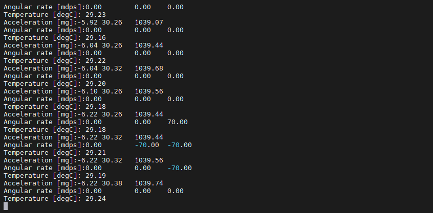
1. 终端输出
复位 Titan Board Mini 后终端会输出如下信息: