Ethernet 示例说明
中文 | English
简介
本示例展示了如何在 Titan Board Mini 上使用 以太网接口,结合 RT-Thread Ethernet 驱动框架 实现网络通信功能。
主要功能包括:
初始化 RA8 系列以太网硬件
配置 IP 地址、子网掩码和网关
发送和接收以太网帧
集成 RT-Thread
netdev框架,实现统一网络设备管理支持 DMA 和中断,实现高速数据传输
以太网(Ethernet)简介
1. 概述
以太网(Ethernet) 是最广泛使用的局域网(LAN)技术,由 Xerox PARC 在 1970 年代提出,后由 IEEE 802.3 标准化。以太网具有以下特点:
数据传输方式:基于 帧(Frame) 的分组交换,物理上可通过双绞线、光纤或无线介质传输。
拓扑结构:传统以太网为总线或星型拓扑,现代以太网主要采用星型和树型。
协议层次:属于 OSI 模型的数据链路层(第 2 层)及物理层(第 1 层)技术。
2. 以太网帧结构
以太网使用 帧(Frame) 作为数据传输单位。以太网帧由以下字段组成:
字段 |
长度 |
描述 |
|---|---|---|
前导码(Preamble) |
7 字节 |
用于帧同步 |
帧开始定界符(SFD) |
1 字节 |
帧起始标志,值为 10101011 |
目的 MAC 地址 |
6 字节 |
接收方硬件地址 |
源 MAC 地址 |
6 字节 |
发送方硬件地址 |
类型/长度 |
2 字节 |
上层协议类型或帧长度 |
数据载荷 |
46~1500 字节 |
上层数据(如 IP 包) |
CRC 校验 |
4 字节 |
循环冗余校验,保证帧完整性 |
最小帧长度:64 字节 最大帧长度:1518 字节(不含 VLAN 标记时)
RA8 系列以太网特性
RA8 系列 MCU(如 RA8P1)集成高性能 以太网 MAC,支持 RGMII、RMII 和 MII 接口,具备稳定可靠的高速网络通信能力。MAC 可配合外部 PHY 使用,并兼容 LwIP TCP/IP 协议栈。
1. 网络接口特性
接口类型
RMII(Reduced Media Independent Interface):节省引脚,支持 10/100 Mbps
MII(Media Independent Interface):标准接口,支持 10/100 Mbps
RGMII(Reduced Gigabit MII):支持 10/100/1000 Mbps,高速接口,适用于千兆以太网
PHY 连接
外部 PHY 通过 MDC/MDIO 接口连接
支持自动协商速率和双工模式
可读取和写入 PHY 寄存器,用于配置和状态监控
2. MAC 特性
双工与速率支持
全/半双工
支持 10/100/1000 Mbps(RGMII)
支持自动协商或强制配置
帧处理
VLAN 标签支持(IEEE 802.1Q,可选)
支持多播和广播帧过滤
硬件 CRC 生成和校验
MAC 地址管理
支持单个或多个 MAC 地址
可通过 FSP 或软件动态配置
3. DMA 与缓冲特性
独立 TX/RX DMA 引擎
支持同时发送和接收数据
减少 CPU 占用,提高吞吐量
描述符队列
TX/RX 缓冲区数量可配置
支持链式 DMA,提高大数据传输效率
多缓冲区管理
支持环形缓冲区,实现连续传输
减少丢包
硬件加速
帧过滤、长度检测和 CRC 校验
4. 中断机制
中断类型
接收完成(RX)
发送完成(TX)
错误中断(CRC 错误、缓冲溢出)
中断配置
优先级可通过 FSP 配置
支持 RT-Thread ISR 集成
优化
RX/TX 中断可与 DMA 联动
可选择性启用中断,提高性能
5. PHY 管理
MDIO 接口
可读写 PHY 寄存器,实现配置、复位和状态监控
自动协商
支持速率(10/100/1000 Mbps)和双工模式自动协商
链路监控
检测链路状态(Up/Down)
CRC 错误和冲突检测
6. 协议与栈支持
TCP/IP 协议栈集成
兼容 LwIP
支持 TCP/UDP/ICMP、DHCP 客户端/服务器、ARP
应用层支持
支持 Telnet、HTTP、MQTT 等应用
多线程安全,支持并发访问
7. 性能与可靠性
吞吐量优化
DMA + 中断减少 CPU 占用
TX/RX 缓冲区大小可调
可靠性特性
硬件 CRC 校验
VLAN 和多播过滤减少干扰
链路检测与自动重连
FSP 配置
注意: 本工程所使用的 FSP 版本为 6.4.0,在使用 FSP 配置功能时请使用 FSP 6.4.0。
新建 r_rmac stack:
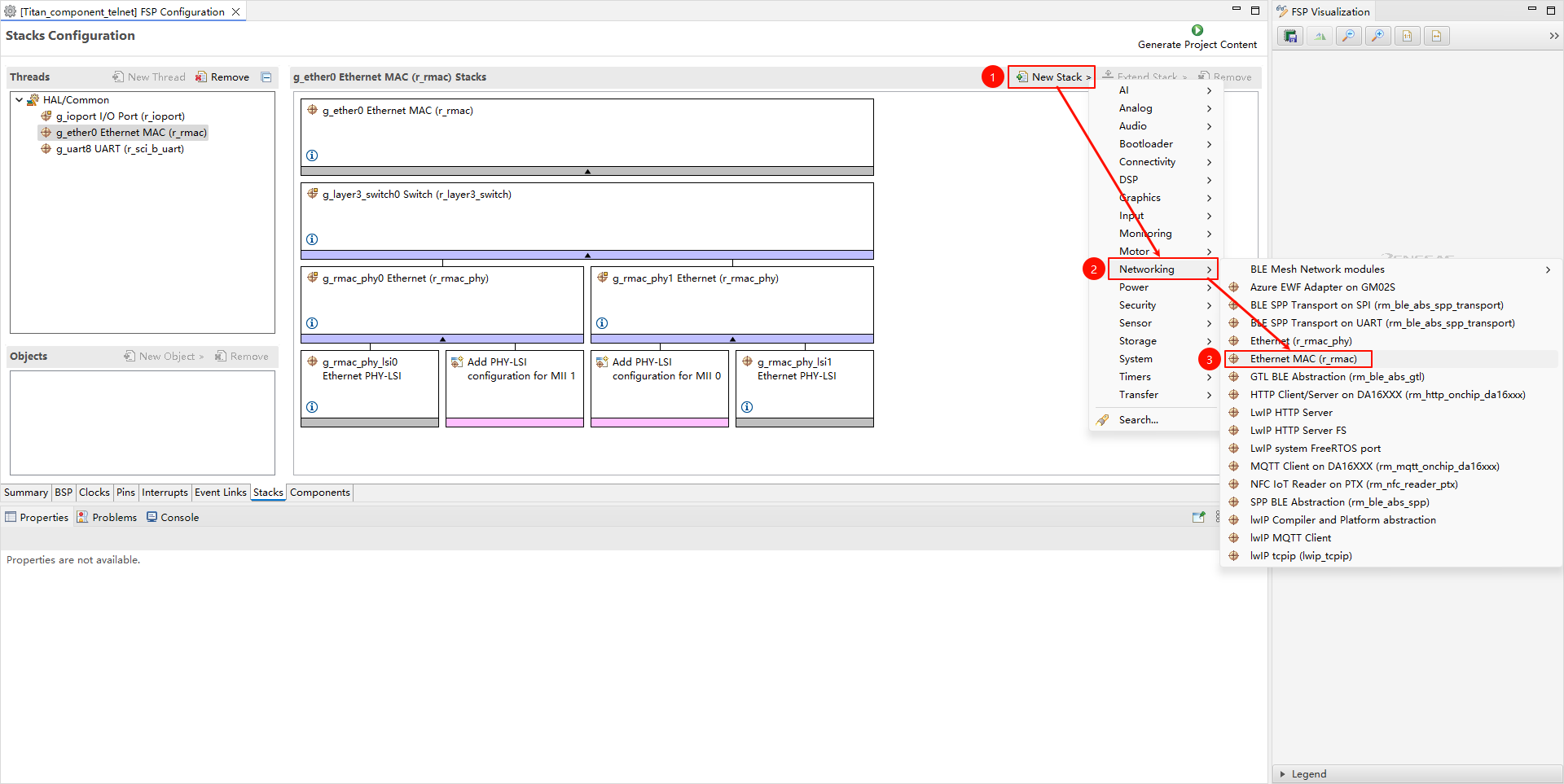
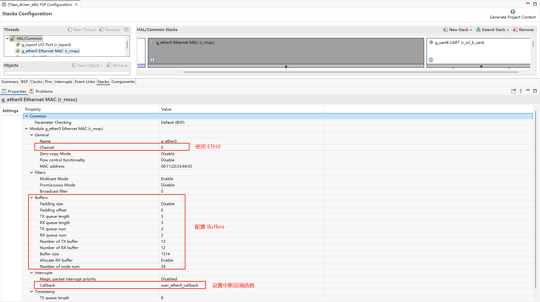
配置 r_mac stack:
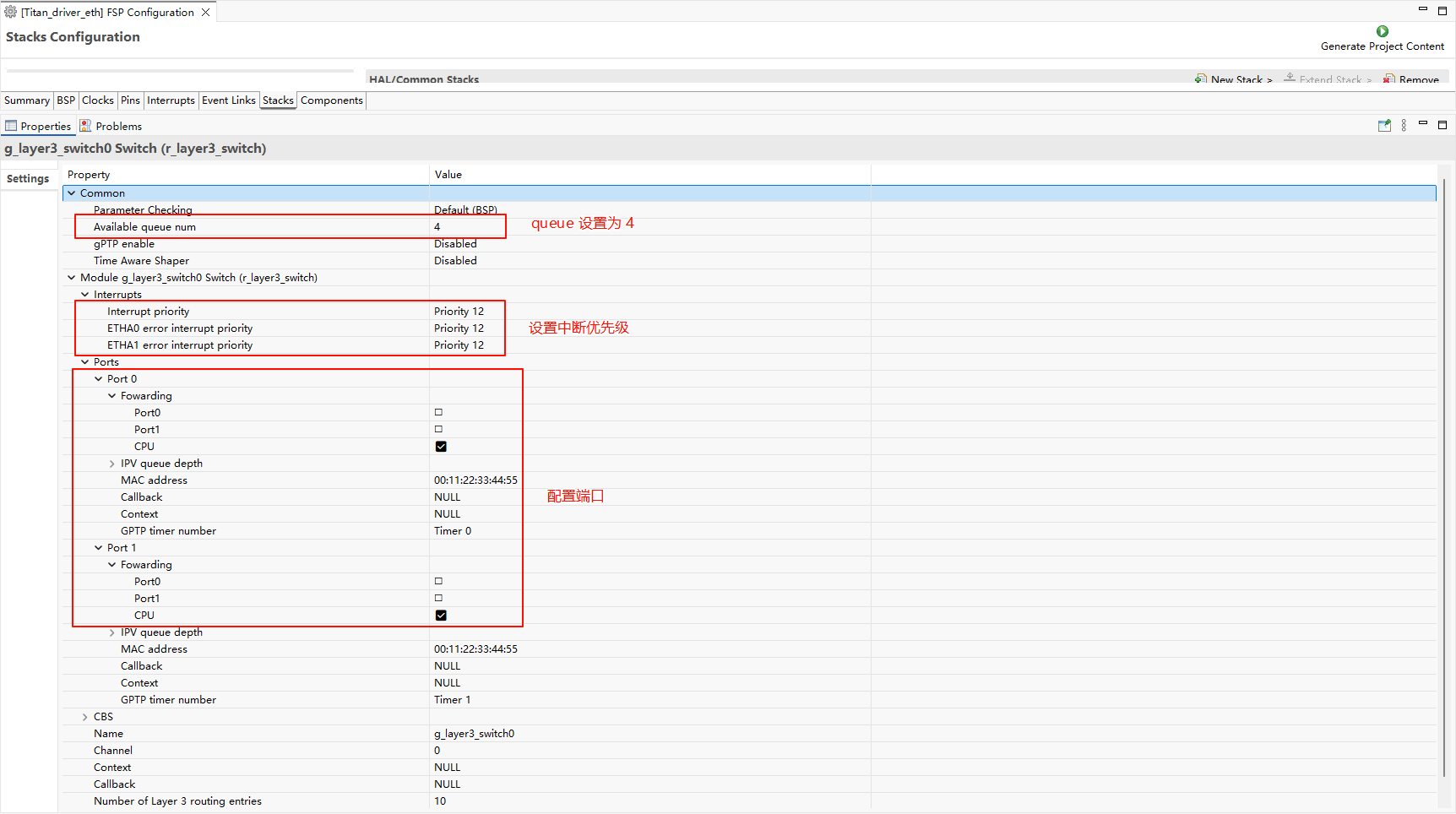
配置 r_layer3_switch:
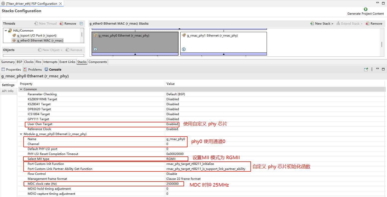
配置 r_rmac_phy:
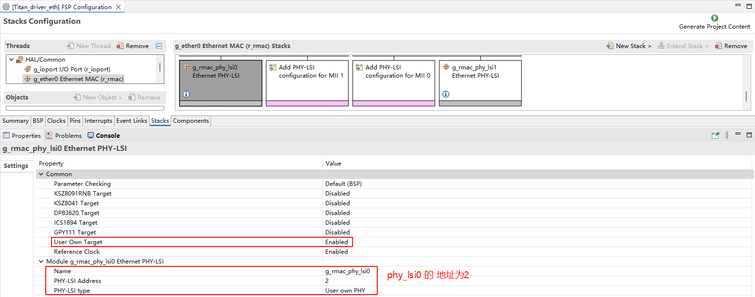
配置 g_rmac_phy_lsi0:
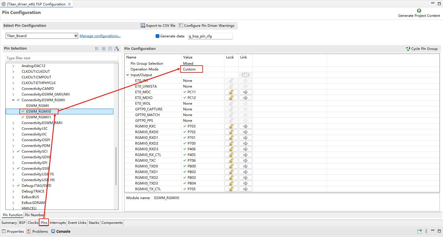
ETH0 引脚配置:
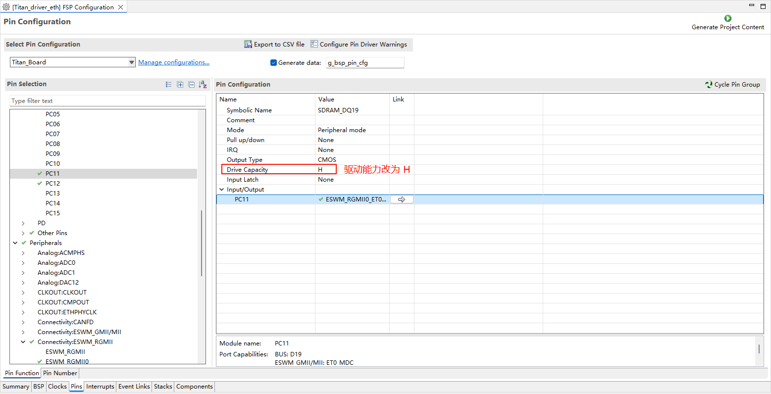
注意:ETH 相关的所有引脚需要将驱动能力改为 H。
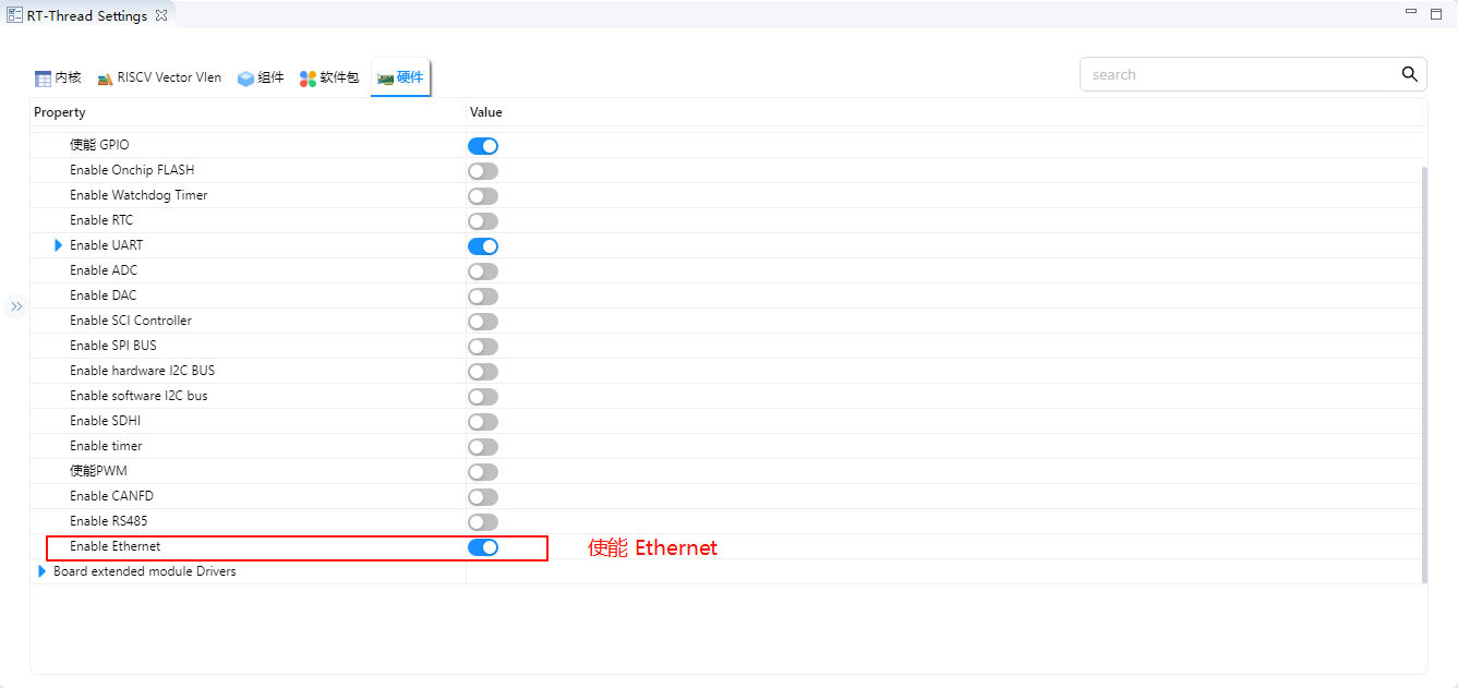
RT-Thread Settings 配置
在 RT-Thread Settings 中使能 Ethernet。
软件说明
LwIP 性能调优建议
RT-Thread 上游 rt-thread/components/net/lwip/Kconfig 中的 LwIP 默认参数偏保守(PBUF 数量 16、TCP 发送缓冲 8196 等),无法充分发挥 RA8P1 千兆以太网 + DMA 的吞吐能力。建议在启用 RT_USING_LWIP(例如勾选 BSP_USING_ETH)后,按下列推荐值手动调优:
参数 |
默认值 |
说明 |
|---|---|---|
|
256 |
PBUF 缓冲池数量(上游默认 16) |
|
4 |
RAW socket 数量 |
|
24 |
UDP PCB 数量(上游默认 4) |
|
24 |
TCP PCB 数量(上游默认 4) |
|
512 |
TCP 段数量(上游默认 40) |
|
65535 |
TCP 发送缓冲(上游默认 8196) |
|
65535 |
TCP 窗口大小(上游默认 8196) |
|
6 |
lwIP 主线程优先级(上游默认 10,数值越小优先级越高) |
|
144 |
lwIP 主线程邮箱大小(上游默认 8) |
|
2048 |
lwIP 主线程栈(上游默认 1024) |
|
y |
不使用独立 TX 线程(发送路径直接调用,减少上下文切换) |
|
5 |
以太网线程优先级(上游默认 12) |
|
2048 |
以太网线程栈(上游默认 1024) |
|
144 |
以太网线程邮箱大小(上游默认 8) |
如需应用上述推荐值,可在 RT-Thread Studio 的 RT-Thread Settings → RT-Thread Components → Network → lwIP 中修改对应项,或直接编辑工程的 .config。
⚠️ 内存占用提示:上述参数对 RAM 占用影响较大。
RT_LWIP_PBUF_NUM=256+TCP_SND_BUF/WND=65535在默认RT_LWIP_PBUF_POOL_BUFSIZE下会预留较多堆内存,请确认链接脚本中 heap 大小足够(建议 ≥ 256 KB)。
编译&下载
RT-Thread Studio:在RT-Thread Studio 的包管理器中下载 Titan Board 资源包,然后创建新工程,执行编译。
编译完成后,将开发板的 USB-DBG 接口与 PC 机连接,然后将固件下载至开发板。
运行效果
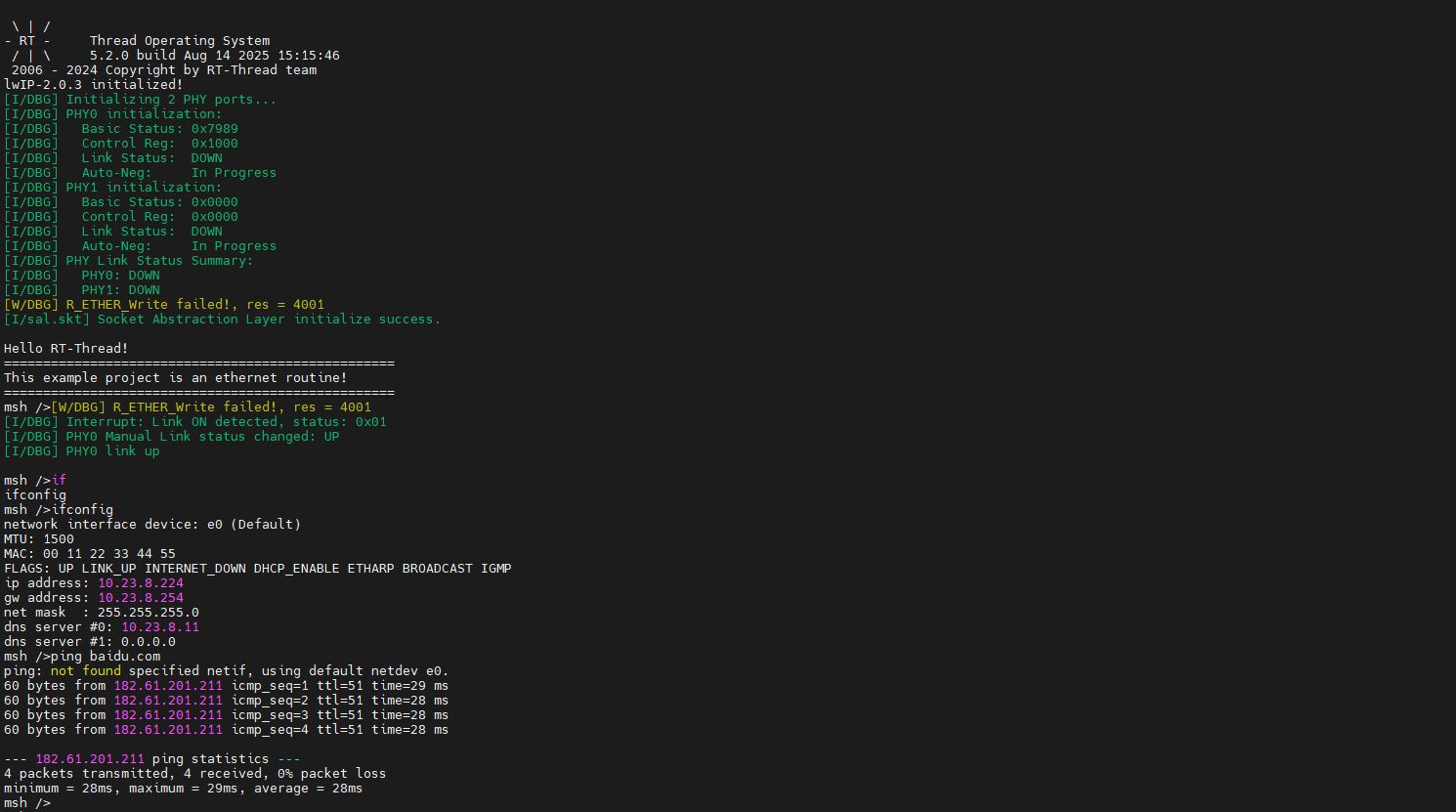
将网线插入 网口,按下复位按键重启开发板,等待 PHY0 link up 之后输入 ifconfig 可以查看开发板获取到的 IP 地址,然后输入 ping baidu.com 命令进行连通性测试。
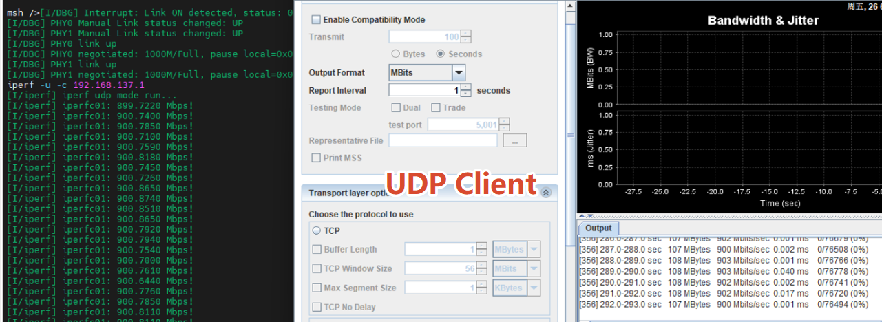
iperf 测试
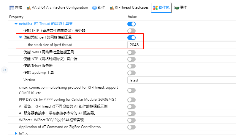
打开 RT-Thread Settings 添加 netutils 软件包并使能 iperf 工具。
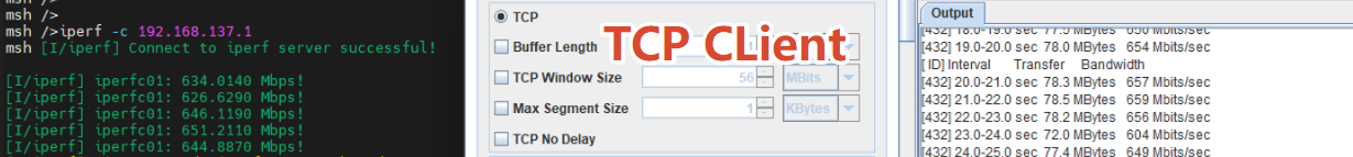
编译下载后在串口终端输入 iperf -c 主机IP -p 5001 进行 iperf 测试。
网络应用示例
借助 netutils 软件包,可以实现 TCP/UDP 的客户端与服务器收发测试。
TCP Client 测试:开发板作为客户端,主动连接远程主机并收发数据。
UDP Client 测试:开发板作为客户端,向远程主机发送或接收数据报。