WDT 驱动示例说明
概述
本工程为基于 RT-Thread 操作系统的 RA8P1 Titan Mini 板看门狗定时器 (Watchdog Timer, WDT) 驱动示例工程。看门狗定时器是嵌入式系统中重要的可靠性组件,用于监控系统运行状态,在系统出现异常时自动复位,保证系统稳定运行。
目录结构
project/Titan_Mini_driver_wdt/
├── src/
│   └── hal_entry.c              # 主入口文件,包含看门狗初始化和喂狗线程
├── ra/
│   ├── fsp/
│   │   └── src/
│   │       └── r_wdt/         # Renesas FSP 看门狗驱动源码
│   └── inc/
│       └── api/
│           └── r_wdt_api.h    # 看门狗 API 接口定义
├── ra_cfg/
│   └── fsp_cfg/
│       └── r_wdt_cfg.h         # 看门狗配置
├── rtconfig.h                  # RT-Thread 配置文件
└── Kconfig                     # 工程配置文件
1. 硬件介绍 - RA8P1的WDT特性
1.1 看门狗概述
看门狗定时器是一种特殊的定时器,用于监控系统运行状态。正常情况下,应用程序需要定期"喂狗"(重置定时器),如果应用程序陷入死循环、跑飞或其他异常状态而无法按时喂狗,看门狗就会触发系统复位,确保系统恢复正常。
1.2 RA8P1 WDT 主要特性
RA8P1 MCU 内置了功能丰富的看门狗定时器,具有以下特性:
1.2.1 基本特性
独立运行: 看门狗独立于主 CPU 运行,即使在 CPU 停止状态下也能继续计数
多种超时时间: 支持 128、512、1024、2048、4096、8192、16384 个时钟周期的超时设置
可配置时钟分频: 支持 1、4、16、32、64、128、256、512、2048、8192 分频
窗口看门狗功能: 支持窗口看门狗模式,只能在特定时间窗口内喂狗
1.2.2 复位模式
复位模式 (Reset Mode): 超时后触发系统复位
NMI 模式 (NMI Mode): 超时后触发不可屏蔽中断 (NMI),用于错误处理和诊断
1.2.3 工作模式
自动启动模式 (Auto-start Mode): 复位后自动启动看门狗
寄存器启动模式 (Register-start Mode): 通过软件控制启动
1.2.4 睡眠模式支持
停止控制: 可配置在睡眠模式下是否停止计数
低功耗优化: 支持低功耗应用场景
1.3 硬件参数配置
根据 hal_entry.c 中的配置:
#define WDT_DEVICE_NAME "wdt"    // 默认看门狗设备名
#define WDT_FEED_INTERVAL 1000   // 喂狗间隔(单位 ms)
#define WDT_TIMEOUT 3            // 看门狗超时时间(单位 s)
2. 软件架构 - RT-Thread看门狗设备框架
2.1 RT-Thread 看门狗驱动架构
RT-Thread 提供了标准化的看门狗设备驱动框架,通过统一的 API 接口操作不同硬件的看门狗模块。
2.1.1 驱动层次结构
应用层
    ↓
RT-Thread 设备驱动层
    ↓
硬件抽象层 (HAL)
    ↓
芯片寄存器操作层
2.1.2 主要组件
设备管理:
rt_device结构体管理设备实例控制接口: 提供启动、停止、喂狗等控制功能
状态查询: 获取看门狗运行状态和计数值
回调机制: 支持看门狗事件回调
2.2 FSP 集成
本工程使用 Renesas Flexible Software Package (FSP) 提供的底层驱动:
2.2.1 FSP 看门狗 API
typedef struct st_wdt_api {
    fsp_err_t (* open)(wdt_ctrl_t * const p_ctrl, wdt_cfg_t const * const p_cfg);
    fsp_err_t (* refresh)(wdt_ctrl_t * const p_ctrl);
    fsp_err_t (* statusGet)(wdt_ctrl_t * const p_ctrl, wdt_status_t * const p_status);
    fsp_err_t (* statusClear)(wdt_ctrl_t * const p_ctrl, const wdt_status_t status);
    fsp_err_t (* counterGet)(wdt_ctrl_t * const p_ctrl, uint32_t * const p_count);
    fsp_err_t (* timeoutGet)(wdt_ctrl_t * const p_ctrl, wdt_timeout_values_t * const p_timeout);
    fsp_err_t (* callbackSet)(wdt_ctrl_t * const p_ctrl, void (* p_callback)(wdt_callback_args_t *),
                              void * const p_context, wdt_callback_args_t * const p_callback_memory);
} wdt_api_t;
2.2.2 配置参数
typedef struct st_wdt_cfg {
    wdt_timeout_t        timeout;                      // 超时时间
    wdt_clock_division_t clock_division;               // 时钟分频
    wdt_window_start_t   window_start;                 // 窗口开始位置
    wdt_window_end_t     window_end;                   // 窗口结束位置
    wdt_reset_control_t  reset_control;                // 复位控制模式
    wdt_stop_control_t   stop_control;                 // 停止控制模式
    void (* p_callback)(wdt_callback_args_t * p_args); // 回调函数
    void * p_context;                                 // 用户上下文
} wdt_cfg_t;
2.3 RT-Thread 设备配置
在 rtconfig.h 中启用看门狗支持:
#define RT_USING_WDT           // 启用看门狗设备支持
#define RT_USING_PIN          // 启用引脚控制支持(用于LED演示)
3. 使用示例 - 基于实际代码的看门狗初始化、喂狗
3.1 主要功能分析
3.1.1 主函数 (hal_entry)
void hal_entry(void)
{
rt_kprintf("\nHello RT-Thread!\n");
rt_kprintf("==================================================\n");
rt_kprintf("This example project is an driver wdt routine!\n");
rt_kprintf("==================================================\n");
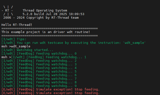
LOG_I("Tips:");
LOG_I("You can run wdt testcase by executing the instruction: \'wdt_sample\'");
while (1)
{
rt_pin_write(LED_PIN_0, PIN_HIGH);
rt_thread_mdelay(1000);
rt_pin_write(LED_PIN_0, PIN_LOW);
rt_thread_mdelay(1000);
}
}
功能说明:
打印欢迎信息和使用提示
LED 闪烁演示(指示系统正常运行)
等待用户执行
wdt_sample命令启动看门狗测试
3.1.2 喂狗线程 (feed_dog_entry)
static void feed_dog_entry(void *parameter)
{
    int count = 0;

    while (1)
    {
        if (count < 10)
        {
            rt_device_control(wdt_dev, RT_DEVICE_CTRL_WDT_KEEPALIVE, RT_NULL);
            LOG_I("[FeedDog] Feeding watchdog... %d", count);
        }
        else
        {
            LOG_E("[FeedDog] Simulate exception! Stop feeding.");
        }

        count++;
        rt_thread_mdelay(WDT_FEED_INTERVAL);
    }
}
功能说明:
创建独立的喂狗线程
前10次正常喂狗,之后停止喂狗模拟系统异常
通过 RT-Thread 设备控制接口实现喂狗操作
3.2 看门狗测试函数 (wdt_sample)
static int wdt_sample(void)
{
    rt_err_t ret;

    // 1. 查找看门狗设备
    wdt_dev = rt_device_find(WDT_DEVICE_NAME);
    if (wdt_dev == RT_NULL)
    {
        LOG_E("Cannot find %s device!", WDT_DEVICE_NAME);
        return -1;
    }

    // 2. 启动看门狗
    ret = rt_device_control(wdt_dev, RT_DEVICE_CTRL_WDT_START, RT_NULL);
    if (ret != RT_EOK)
    {
        LOG_E("Start watchdog failed!");
        return -1;
    }

    LOG_I("Watchdog started...", WDT_TIMEOUT);

    // 3. 创建并启动喂狗线程
    feed_thread = rt_thread_create("feed_dog", feed_dog_entry, RT_NULL, 1024, 10, 10);
    if (feed_thread != RT_NULL)
        rt_thread_startup(feed_thread);

    return 0;
}
3.2.1 详细步骤解析
步骤1:查找设备
wdt_dev = rt_device_find(WDT_DEVICE_NAME);
使用
rt_device_find()函数查找名为 “wdt” 的设备返回设备句柄,后续操作使用此句柄
步骤2:启动看门狗
ret = rt_device_control(wdt_dev, RT_DEVICE_CTRL_WDT_START, RT_NULL);
使用
rt_device_control()函数发送控制命令RT_DEVICE_CTRL_WDT_START启动看门狗返回操作状态码
步骤3:创建喂狗线程
feed_thread = rt_thread_create("feed_dog", feed_dog_entry, RT_NULL, 1024, 10, 10);
创建名为 “feed_dog” 的线程
入口函数为
feed_dog_entry栈大小 1024 字节
优先级 10,时间片 10
3.3 RT-Thread 看门狗 API
3.3.1 设备查找和控制
// 查找设备
rt_device_t rt_device_find(const char *name);

// 设备控制
rt_err_t rt_device_control(rt_device_t dev, int cmd, void *arg);
常用控制命令:
RT_DEVICE_CTRL_WDT_START: 启动看门狗RT_DEVICE_CTRL_WDT_STOP: 停止看门狗RT_DEVICE_CTRL_WDT_KEEPALIVE: 喂狗操作
3.3.2 线程操作
// 创建线程
rt_thread_t rt_thread_create(const char *name,
                           void (*entry)(void *parameter),
                           void *parameter,
                           size_t stack_size,
                           rt_int32_t priority,
                           rt_uint32_t tick);

// 启动线程
rt_err_t rt_thread_startup(rt_thread_t thread);

// 延时
void rt_thread_mdelay(rt_int32_t ms);
4. 配置说明 - 超时时间、复位模式
4.1 超时时间配置
4.1.1 硬件层面的超时设置
RA8P1 WDT 支持多种超时时间配置:
// 超时时间枚举
typedef enum e_wdt_timeout {
    WDT_TIMEOUT_128   = 0,    // 128 个时钟周期
    WDT_TIMEOUT_512   = 1,    // 512 个时钟周期
    WDT_TIMEOUT_1024  = 2,    // 1024 个时钟周期
    WDT_TIMEOUT_2048  = 3,    // 2048 个时钟周期
    WDT_TIMEOUT_4096  = 4,    // 4096 个时钟周期
    WDT_TIMEOUT_8192  = 5,    // 8192 个时钟周期
    WDT_TIMEOUT_16384 = 6,    // 16384 个时钟周期
} wdt_timeout_t;
4.2 复位模式配置
4.2.1 复位模式选择
// 复位控制枚举
typedef enum e_wdt_reset_control {
    WDT_RESET_CONTROL_NMI   = 0,  // NMI/IRQ 请求模式
    WDT_RESET_CONTROL_RESET = 1,  // 复位模式
} wdt_reset_control_t;
4.2.2 模式特性对比
模式 |
特点 |
适用场景 |
|---|---|---|
复位模式 |
超时后直接触发系统复位 |
一般应用,需要自动恢复 |
NMI模式 |
超时后触发不可屏蔽中断 |
诊断和调试,需要在复位前处理 |
5.WDT工程配置
首先需要在RT-Thread Studio Settings打开Watchdog Timer
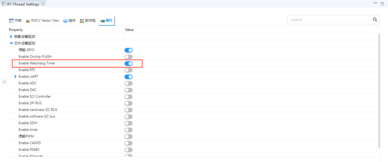
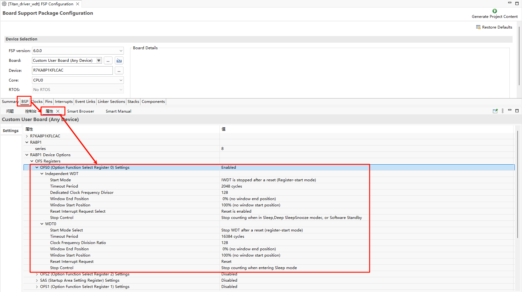
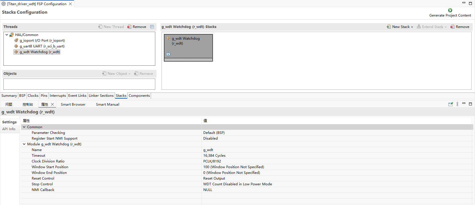
随后使用 Renesas Flexible Software Package (FSP) 进行硬件配置,如下图
5. 运行效果示例
5.1 正常运行流程
结论
RA8P1 Titan Mini 板看门狗定时器驱动工程通过精心设计和实现,提供了一个稳定、可靠的看门狗解决方案。该方案不仅满足了基本的看门狗功能需求,还具备良好的扩展性和实用性,适用于各种嵌入式应用场景。