GPT 驱动示例说明
中文 | English
简介
本示例项目展示如何在 Titan Board Mini (基于 RA8P1) 上使用 RT-Thread 定时器设备驱动框架 来实现 GPT(通用PWM定时器)功能。
核心功能特性
PWM 波形生成:支持多种PWM模式(方波、三角波等)
高精度定时:32位高分辨率计数器
多通道支持:同时管理多个定时器通道
输入捕获:测量外部信号频率和脉冲宽度
灵活配置:支持多种时钟源和工作模式
实时控制:微秒级精度的定时控制
技术栈
硬件平台:Renesas RA8P1 (Cortex-M85 + Cortex-M33)
操作系统:RT-Thread 实时操作系统
开发工具:RT-Thread Studio
驱动框架:Renewas FSP (Flexible Software Package)
硬件介绍
1. RA8P1 微控制器特性
RA8P1 是 Renesas 的高性能32位微控制器,专为人工智能和机器学习应用设计:
核心规格
CPU架构:双核异构架构
Cortex-M85:1GHz主频,Helium™向量扩展
Cortex-M33:250MHz主频,TrustZone安全架构
NPU加速:集成Ethos™-55 NPU,256 GOPS AI算力
存储配置:2MB SRAM,支持ECC校验
时钟系统:支持多源时钟,最高1GHz
定时器资源
GPT定时器:多个32位通用PWM定时器
AGT定时器:异步16位定时器
分辨率:最高32位计数器精度
时钟源:PCLK、外部触发、事件链控制
2. GPT 硬件模块详解
2.1 GPT 模块架构
┌─────────────────────────────────────────────────────────┐
│                   GPT 定时器模块                        │
├─────────────────────────────────────────────────────────┤
│  定时器控制单元     ▲     PWM比较单元                    │
│  (Timer Control)    │    (PWM Compare)                  │
│                     │                                  │
│  计数器逻辑         │     输出控制                      │
│  (Counter Logic)    │     (Output Control)              │
│                     │                                  │
│  输入捕获单元       │     中断控制器                    │
│  (Input Capture)    │     (Interrupt Ctrl)              │
│                     │                                  │
│  时钟选择单元       │     滤波器                        │
│  (Clock Select)     │     (Filter)                      │
└─────────────────────────────────────────────────────────┘
2.2 GPT 核心特性
工作模式
周期模式 (Periodic):持续输出固定周期的脉冲
单次模式 (One-Shot):仅输出一个脉冲后停止
PWM模式:生成可变占空比的PWM波形
方波PWM (Square Wave PWM)
锯齿波PWM (Saw Wave PWM)
三角波PWM (Triangle Wave PWM)
性能指标
分辨率:32位计数器 (0-4,294,967,295)
时钟频率:最高可达PCLKD/1 (PCLKD支持100MHz+)
输出精度:纳秒级精度
通道数量:每个GPT模块支持多个PWM通道
硬件接口
输出引脚:GTIOCA, GTIOCB (支持极性控制)
输入引脚:支持外部信号触发和测量
事件链:支持与ELC (事件链控制器) 集成
滤波功能:支持输入信号去抖滤波
2.3 RA8P1 GPT 实际配置
基于当前项目配置,Titan Board Mini 的GPT配置如下:
时钟配置
主时钟源:PCLKD
分频系数:可配置 (1-1024)
频率范围:根据系统时钟动态配置
引脚分配
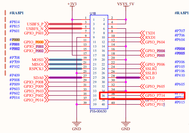
PWM输出:P714
输入捕获:支持多路GPIO
触发源:外部信号或软件触发
软件架构
1. RT-Thread 设备框架
1.1 设备层次结构
┌─────────────────────────────────────────────────────────┐
│                  RT-Thread 内核                         │
├─────────────────────────────────────────────────────────┤
│                设备管理层                               │
│  ┌─────────────┐  ┌─────────────┐  ┌─────────────┐    │
│  │  PWM设备    │  │  HWTIMER    │  │   其他设备   │    │
│  │   (pwm12)   │  │  设备       │  │  管理器      │    │
│  └─────────────┘  └─────────────┘  └─────────────┘    │
├─────────────────────────────────────────────────────────┤
│              驱动抽象层                                 │
│  ┌─────────────────────────────────────────────────────┐ │
│  │             GPT 驱动层                               │ │
│  │  ┌─────────────┐  ┌─────────────┐  ┌─────────────┐ │ │
│  │  │ FSP适配层  │  │ PWM控制    │  │ 中断处理    │ │ │
│  │  │  (r_gpt)   │  │ (rt_pwm)   │  │ (R_GPT)     │ │ │
│  │  └─────────────┘  └─────────────┘  └─────────────┘ │ │
│  └─────────────────────────────────────────────────────┘ │
├─────────────────────────────────────────────────────────┤
│              硬件抽象层                                 │
│  ┌─────────────────────────────────────────────────────┐ │
│  │            RA8P1 硬件接口                         │ │
│  │  ┌─────────────┐  ┌─────────────┐  ┌─────────────┐ │ │
│  │  │  GPT寄存器  │  │ 中断控制器 │  │ GPIO控制    │ │ │
│  │  │  操作接口   │  │    NVIC     │  │    PORT     │ │ │
│  │  └─────────────┘  └─────────────┘  └─────────────┘ │ │
│  └─────────────────────────────────────────────────────┘ │
└─────────────────────────────────────────────────────────┘
1.2 核心接口函数
设备控制接口
// PWM设备查找
rt_device_pwm *rt_device_find(const char *name);

// PWM配置设置
rt_err_t rt_pwm_set(rt_device_pwm *device, int channel,
                   rt_uint32_t period, rt_uint32_t pulse);

// PWM使能控制
rt_err_t rt_pwm_enable(rt_device_pwm *device, int channel);
rt_err_t rt_pwm_disable(rt_device_pwm *device, int channel);

// HWTIMER接口
rt_err_t rt_device_find(const char *name);
rt_err_t rt_hwtimer_control(rt_device_t dev, int cmd, void *arg);
中断处理接口
// GPT中断服务函数
void timer1_callback(timer_callback_args_t *p_args);

// 中断配置
void R_GPT_Open(gpt_instance_ctrl_t *p_ctrl, const timer_cfg_t *const p_cfg);
void R_GPT_Start(gpt_instance_ctrl_t *p_ctrl);
void R_GPT_Stop(gpt_instance_ctrl_t *p_ctrl);
2. 驱动程序架构
2.1 主要驱动文件
project/Titan_Mini_driver_gpt/
├── src/hal_entry.c              # 主程序入口
├── ra/src/r_gpt/r_gpt.c        # FSP GPT驱动实现
├── ra/inc/instances/r_gpt.h     # GPT头文件
├── ra_cfg/fsp_cfg/r_gpt_cfg.h   # GPT配置文件
└── ra_gen/hal_data.h           # 硬件抽象层
使用示例
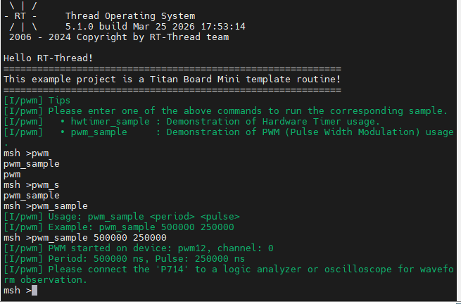
本工程已经把 GPT 示例导出为 pwm_sample MSH 命令,可在串口终端中按照下列步骤体验:
复位开发板后,打开串口终端并输入
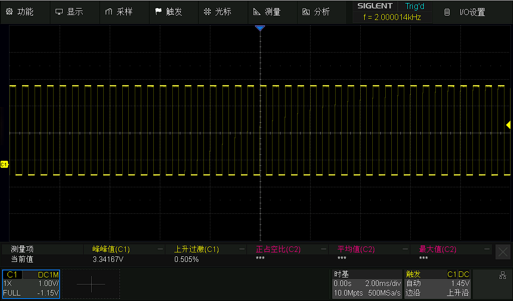
pwm_sample <period> <pulse>。period、pulse单位均为纳秒,例如pwm_sample 500000 250000表示输出 2 kHz、占空比 50% 的 PWM。命令运行成功后,串口会提示当前使用的设备(
pwm12)以及周期/脉宽配置。将示波器或逻辑分析仪接到
P714引脚,即可观测到实时 PWM 波形。如果需要停止输出,可重新上电或在命令中输入新的
period/pulse参数覆盖。
配置说明
若需要在自己的工程中复用本示例配置,可按以下步骤操作:
FSP(configuration.xml)
新建
r_gptStack 并选择与本项目一致的 GPT 通道(示例中为pwm12)。将工作模式设为 PWM,启用输出管脚(例如 GTIOC 的
P714),并根据需要配置时钟源/分频。
RT-Thread Settings
在
Device Drivers -> PWM中勾选 PWM 驱动,使系统注册pwm12设备。如果需要在开机自动运行,可以把
pwm_sample命令封装到组件初始化函数中。
硬件连接
P714引脚默认连接到 GPT 通道 12 的输出端,示例通过该引脚驱动外部负载,需根据实际应用外接 MOSFET/LED/测试点。
运行效果示例
在终端输入pwm_sample 500000 250000运行示例
随后将其P714引脚接入到示波器中可以查看到效果,如下图
如有问题或建议,欢迎在 RT-Thread 官方论坛 中提出讨论。