ADC 驱动示例
中文 | English
简介
本示例展示如何在 Titan Board Mini 上基于 RT-Thread ADC 设备驱动框架 实现 RA8P1 微控制器的模数转换功能。该工程提供了完整的 ADC 初始化、采样、电压转换和线程管理的综合解决方案。
主要特性
RA8P1 ADC 硬件抽象层 - 完整的 16 位 ADC 驱动支持
RT-Thread 设备框架集成 - 标准化的设备管理和控制接口
多线程并发处理 - 后台线程持续采样和数据显示
实时电压转换 - 模拟信号到数字信号的精确转换
低功耗设计 - 支持动态使能/禁用 ADC 通道
命令行接口 - 通过
adc_sample命令快速启动采样
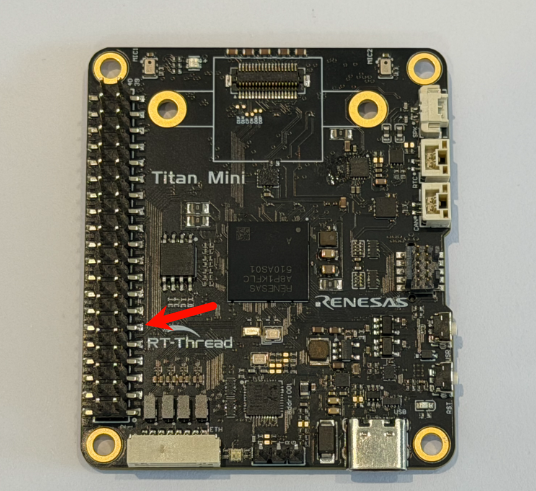
1. 硬件介绍
1.1 RA8P1 微控制器概述
RA8P1 是 Renesas 公司推出的高性能 ARM Cortex-M85 微控制器,专为边缘 AI 和实时应用而设计:
核心架构: ARM Cortex-M85 @ 1GHz(支持 Helium MVE 向量扩展)
协处理器: ARM Cortex-M33 @ 250MHz(实时控制核心)
内存配置: 2MB SRAM(含 ECC 校验),支持 TCM(紧密耦合内存)
AI 加速: 内置 Ethos-U55 NPU,支持神经网络推理
1.2 ADC 硬件特性
RA8P1 集成了先进的模拟数字转换子系统:
1.2.1 ADC 核心参数
参数 |
规格 |
说明 |
|---|---|---|
分辨率 |
16 位 |
高精度转换,最大 65536 个量化等级 |
采样率 |
最高 23 通道 |
多通道同步采样支持 |
参考电压 |
3.3V(文中按 0.01V 精度即 330) |
内置高精度电压基准 |
数据接口 |
16 位并行 |
高速数据传输接口 |
DMA 支持 |
8 通道 DMA |
无 CPU 干扰的数据采集 |
1.2.2 ADC 电气特性
// 参考电压配置
#define REFER_VOLTAGE       330     // 3.30V × 100 (精度保留2位小数)
#define CONVERT_BITS        ((1 << 16) - 1) // 16位分辨率 = 65535

// 电压计算公式
// 实际电压(mV) = ADC读数 × 参考电压(mV) / 转换位数
// 电压(V) = (ADC读数 × 3.3V) / 65535
1.2.3 ADC 通道配置
通道数量: 23 个模拟输入通道
通道选择: 可通过软件动态配置
输入范围: 0V ~ 3.3V 单极性输入
采样保持: 内置采样保持电路
触发方式: 软件触发、定时器触发、外部事件触发
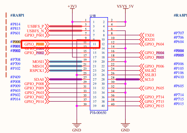
1.3 硬件连接图
2. 软件架构
2.1 RT-Thread ADC 驱动框架
RT-Thread 提供了统一的 ADC 设备驱动框架,支持多种微控制器平台:
2.1.1 设备管理接口
// ADC 设备管理核心接口
rt_err_t rt_adc_enable(rt_adc_device_t dev, rt_uint32_t channel);    // 使能 ADC 通道
rt_err_t rt_adc_disable(rt_adc_device_t dev, rt_uint32_t channel);   // 禁用 ADC 通道
rt_uint32_t rt_adc_read(rt_adc_device_t dev, rt_uint32_t channel);   // 读取 ADC 值
2.1.2 设备生命周期
设备初始化 → 设备查找 → 设备使能 → 数据采样 → 设备禁用 → 资源释放
     ↓           ↓         ↓        ↓        ↓         ↓
   rt_device_init  rt_device_find  rt_adc_enable  rt_adc_read  rt_adc_disable  rt_device_close
2.2 项目软件架构
Titan_Mini_driver_adc/
├── src/
│   └── hal_entry.c          # 主入口文件,包含ADC采样逻辑
├── Kconfig                   # RT-Thread配置
├── SConstruct                # 构建脚本
├── libraries/               # HAL库文件
│   └── HAL_Drivers/         # 硬件抽象层驱动
└── rt-thread/               # RT-Thread内核
    └── components/
        └── drivers/          # 设备驱动框架
2.2.1 模块划分
模块 |
功能 |
文件位置 |
|---|---|---|
应用层 |
用户接口和业务逻辑 |
|
设备层 |
ADC设备管理 |
|
硬件层 |
底层硬件驱动 |
|
配置层 |
系统配置 |
|
2.3 程序执行流程
// 主程序执行流程
void hal_entry(void) {
    // 1. 初始化系统
    rt_kprintf("Hello RT-Thread!\n");

    // 2. 配置LED指示灯
    rt_pin_mode(LED_PIN_R, PIN_MODE_OUTPUT);

    // 3. 进入主循环(LED闪烁)
    while(1) {
        rt_pin_write(LED_PIN_R, PIN_LOW);
        rt_thread_mdelay(500);
        rt_pin_write(LED_PIN_R, PIN_HIGH);
        rt_thread_mdelay(500);
    }
}

// ADC采样线程启动
void adc_sample() {
    // 创建独立线程执行ADC采样
    rt_thread_t adc_thread = rt_thread_create(
        "adc",           // 线程名
        adc_vol_sample,  // 线程入口函数
        RT_NULL,         // 线程参数
        1024,            // 线程栈大小
        10,              // 优先级
        10               // 时间片
    );
    rt_thread_startup(adc_thread);
}
3. 使用示例
3.1 基础 ADC 采样
3.1.1 设备初始化和查找
// ADC设备配置常量
#define ADC_DEV_NAME        "adc0"      // ADC设备名称
#define ADC_DEV_CHANNEL     0           // ADC通道号
#define REFER_VOLTAGE       330         // 参考电压(3.3V × 100)
#define CONVERT_BITS        ((1 << 16) - 1)    // 16位分辨率(0~65535)

// ADC设备初始化函数
int adc_vol_sample()
{
    rt_adc_device_t adc_dev;           // ADC设备句柄
    rt_uint32_t value, vol;            // ADC值和电压值
    rt_err_t ret = RT_EOK;             // 返回状态码

    // 1. 查找ADC设备
    adc_dev = (rt_adc_device_t)rt_device_find(ADC_DEV_NAME);
    if (adc_dev == RT_NULL)
    {
        rt_kprintf("adc sample run failed! can't find %s device!\n", ADC_DEV_NAME);
        return RT_ERROR;
    }

    // 2. 使能ADC通道
    ret = rt_adc_enable(adc_dev, ADC_DEV_CHANNEL);
    if (ret != RT_EOK)
    {
        rt_kprintf("adc enable failed! ret = %d\n", ret);
        return ret;
    }

    // 3. 进入采样循环
    while(1)
    {
        // 4. 读取ADC原始值
        value = rt_adc_read(adc_dev, ADC_DEV_CHANNEL);
        rt_kprintf("the value is :%d \n", value);

        // 5. 转换为电压值(单位: mV)
        vol = value * REFER_VOLTAGE / CONVERT_BITS;
        rt_kprintf("the voltage is :%d.%02d \n", vol / 100, vol % 100);

        // 6. 延时1秒
        rt_thread_mdelay(1000);
    }

    // 7. 禁用ADC通道(理论上不会执行到这里)
    ret = rt_adc_disable(adc_dev, ADC_DEV_CHANNEL);
    return ret;
}
3.1.2 电压计算详解
电压转换采用定点数计算方式,保证精度:
// 原始ADC值范围: 0 ~ 65535 (16位)
// 参考电压: 3.3V = 330 (以 0.01V 精度表示)
// 转换公式: 电压(mV) = (ADC值 × 33000mV) / 65535

// 示例计算:
// 当ADC读取值为 32768 (接近满量程的一半)
vol = 32768 * 330 / 65535;
// vol ≈ 16500 (以0.01V计) -> 1.65V

// 显示格式化输出:
// vol / 100 = 165   (整数部分,伏特)
// vol % 100 = 0     (小数部分,百分之一伏特)
// 输出: "the voltage is :165.00"
3.2 多线程实现
3.2.1 线程创建和启动
// 创建ADC采样线程
void adc_sample()
{
    rt_thread_t adc = rt_thread_create("adc", adc_vol_sample, RT_NULL, 1024, 10, 10);

    // 启动线程
    if (adc != RT_NULL)
    {
        rt_thread_startup(adc);
        rt_kprintf("ADC sampling thread started successfully!\n");
    }
    else
    {
        rt_kprintf("Failed to create ADC sampling thread!\n");
    }
}

// 导出为MSH命令
MSH_CMD_EXPORT(adc_sample, adc_sample);
3.2.2 线程同步机制
RT-Thread 提供了丰富的线程同步机制:
// 可以添加互斥锁保护ADC设备访问
static rt_mutex_t adc_mutex = RT_NULL;

// 在ADC初始化中创建互斥锁
rt_mutex_init(&adc_mutex, "adc_mutex", RT_IPC_FLAG_FIFO);

// 在ADC采样中使用互斥锁
rt_mutex_take(adc_mutex, RT_WAITING_FOREVER);
// 执行ADC操作
rt_mutex_release(adc_mutex);
3.3 命令行接口使用
3.3.1 终端命令
# 1. 探查ADC设备是否存在
msh >adc probe adc0
probe adc0 success

# 2. 启动ADC采样(本程序提供的命令)
msh >adc_sample
ADC sampling thread started successfully!

# 3. 使用RT-Thread内置命令管理ADC
msh >adc enable 0
adc0 channel 0 enables success

msh >adc read 0
adc0 channel 0 read value is 0x1234

msh >adc disable 0
adc0 channel 0 disable success
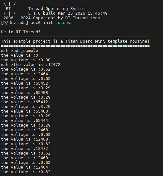
4. 运行效果
4.1 终端输出示例
4.1.1 启动信息
找一根杜邦线,将其3.3V与其ADC引脚连接,如下图
随后通过串口终端运行示例adc_sample
5. 参考资源
5.1 技术文档
RT-Thread 官方文档