SPI 驱动示例说明
English | 中文
项目介绍
本示例演示如何在 Titan Board Mini 开发板上使用 RT-Thread SPI 设备驱动框架 进行串行外设接口通信。基于 RA8P1 微控制器的硬件 SPI 外设,支持多种通信模式和高速数据传输。
主要特性
RA8P1 硬件 SPI 初始化与配置
SPI 主模式通信
DMA 支持的高速传输
多种 SPI 设备集成支持
目录结构
Titan_Mini_driver_spi/
├── src/
│   └── hal_entry.c          # 主要的SPI驱动代码
├── ra/
│   ├── fsp/src/r_spi_b/     # SPI底层驱动实现
│   └── hal_data.c          # 硬件抽象层配置
├── ra_gen/
│   └── hal_data.c          # 生成的硬件配置
├── libraries/
│   └── M85_Config/
└── README_zh.md            # 中文文档
1. 硬件介绍 - RA8P1 的 SPI 特性
1.1 RA8P1 微控制器概述
RA8P1 是 Renesas RA 系列的 32 位 ARM Cortex-M33 微控制器,专为嵌入式应用设计,具有强大的外设接口和低功耗特性。
1.2 SPI 硬件特性
1.2.1 多通道支持
SPI0: 支持 2 个通道
SPI1: 支持 2 个通道
SPI2: 支持 2 个通道
SPI3: 支持 1 个通道
SPI4: 支持 1 个通道
OSPI: 1 个 OctoSPI 通道
1.2.2 高速传输特性
最高时钟频率: 25 MHz (取决于系统配置)
DMA 支持: 双向 DMA 传输,减少 CPU 负担
数据位宽: 支持 1-16 位可配置数据宽度
传输模式: 支持主模式和从模式
1.2.3 时钟配置特性
时钟极性 (CPOL): 可配置高电平或低电平空闲
时钟相位 (CPHA): 可配置边沿触发方式
时钟分频: 支持 2-4096 分频
时钟源: 可选择多种时钟源
1.2.4 片选控制
多片选支持: 支持多个从设备
软件控制: 可通过软件控制片选信号
硬件控制: 可自动管理片选信号
极性配置: 支持高电平或低电平有效
1.3 SPI 引脚映射
Titan Board Mini SPI1 引脚配置
SPI1 引脚定义(RA8 命名):
- MOSI (主出从入):  P708 / BSP_IO_PORT_07_PIN_08
- MISO (主入从出):  P709 / BSP_IO_PORT_07_PIN_09
- SCLK (时钟):      P102 / BSP_IO_PORT_01_PIN_02
- SS (片选):        P105 / BSP_IO_PORT_01_PIN_05
注意: 实际引脚配置可能根据项目设置有所变化,请参考具体的硬件连接。
2. 软件架构 - RT-Thread SPI 设备框架
2.1 RT-Thread SPI 架构概览
RT-Thread 提供了完整的 SPI 设备驱动框架,采用分层架构设计:
应用程序层
    ↓
SPI 设备层 (rt_spi_device)
    ↓
SPI 总线层 (rt_spi_bus)
    ↓
SPI 操作层 (rt_spi_ops)
    ↓
硬件抽象层 (HAL)
2.2 主要数据结构
2.2.1 SPI 配置结构
struct rt_spi_configuration {
    rt_uint8_t mode;          /* 工作模式 */
    rt_uint8_t data_width;    /* 数据位宽 */
    rt_uint16_t reserved;     /* 保留字段 */
    rt_uint32_t max_hz;       /* 最大传输频率 */
};
2.2.2 SPI 设备结构
struct rt_spi_device {
    struct rt_device parent;          /* 父设备 */
    struct rt_spi_bus *bus;          /* 总线 */
    struct rt_spi_configuration config; /* 配置 */
    rt_base_t cs_pin;                /* 片选引脚 */
    void *user_data;                 /* 用户数据 */
};
2.3 SPI 工作模式
2.3.1 主从模式
主模式 (RT_SPI_MASTER): 发起数据传输,控制时钟信号
从模式 (RT_SPI_SLAVE): 响应主设备命令,接收时钟信号
2.3.2 时钟模式
#define RT_SPI_MODE_0   (0 | 0)        /* CPOL=0, CPHA=0 */
#define RT_SPI_MODE_1   (0 | RT_SPI_CPHA)   /* CPOL=0, CPHA=1 */
#define RT_SPI_MODE_2   (RT_SPI_CPOL | 0)   /* CPOL=1, CPHA=0 */
#define RT_SPI_MODE_3   (RT_SPI_CPOL | RT_SPI_CPHA) /* CPOL=1, CPHA=1 */
2.3.3 数据传输模式
MSB 优先: 数据从高位开始传输
LSB 优先: 数据从低位开始传输
2.4 核心 API 接口
2.4.1 设备查找
struct rt_spi_device *rt_device_find(const char *name);
2.4.2 设备配置
rt_err_t rt_spi_configure(struct rt_spi_device *device,
                          struct rt_spi_configuration *cfg);
2.4.3 数据传输
rt_size_t rt_spi_transfer(struct rt_spi_device *device,
                          const void *send_buf,
                          void *recv_buf,
                          rt_size_t length);
2.4.4 设备附加
rt_err_t rt_hw_spi_device_attach(const char *bus_name,
                               const char *device_name,
                               void *user_data);
3. 运行效果示例
使用杜邦线短接开发板树莓派扩展接口的 P708 与 P709 引脚(连接位置如下图所示),以构建回环测试,如下图的位置
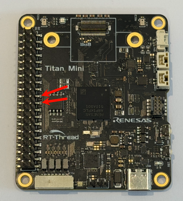
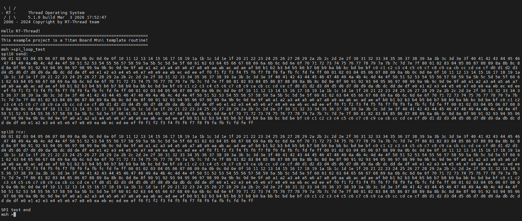
完成硬件连接后,编译工程并将固件烧录至开发板。打开串口终端,输入命令 spi_loop_test,即可观察到测试结果
参考文档: