Edgi-Talk_Key_Irq Example Project
中文 | English
Introduction
This example project is based on the Edgi-Talk platform, running on the RT-Thread real-time operating system, demonstrating the usage of Key IRQ (Button Interrupts). Through this project, users can learn how to configure GPIO interrupts in RT-Thread and implement button-triggered event responses, providing a reference for future human-machine interaction applications.
MCU Interrupt System Overview
Key interrupt features:
NVIC (Nested Vector Interrupt Controller)
Supports interrupt nesting: high-priority interrupts can preempt lower-priority ones
Supports priority grouping (Preemption Priority and Subpriority)
IRQn maps to the interrupt vector table, and NVIC calls the corresponding ISR
GPIO External Interrupt (EXTI)
Each GPIO pin can be configured as an external interrupt input
Supports rising edge, falling edge, or both edges trigger
Interrupt channels are managed by the ICU (Interrupt Controller Unit)
Configurable via Renesas FSP or low-level registers
Low response latency, suitable for buttons, sensors, and other event-driven inputs
RT-Thread PIN Driver Model
GPIOs are encapsulated as PIN devices in RT-Thread
Provides a unified interface:
rt_pin_mode(pin, mode): configure input/output modert_pin_read(pin)/rt_pin_write(pin, value): read/write GPIOrt_pin_attach_irq(pin, mode, callback, args): register interrupt callbackrt_pin_irq_enable(pin, enable): enable/disable interrupt
Using the RT-Thread PIN driver, you can handle interrupts without directly manipulating NVIC or MCU registers.
Hardware Description
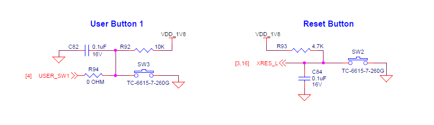
Button Interface
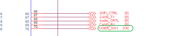
BTB Socket
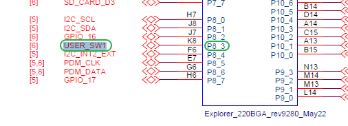
MCU Interface
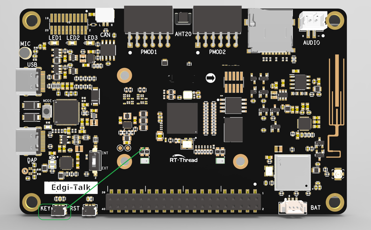
Physical Board Location
Software Description
Developed on the Edgi-Talk platform.
Uses RT-Thread as the OS kernel.
Example features include:
Configure button GPIO as interrupt input
Trigger interrupt callback when the button is pressed
Blue LED blinks at a 500ms period, indicating normal system operation
Usage
Build and Download
Open the project and compile it.
Connect the board’s USB interface to the PC using the onboard debugger (DAP).
Flash the generated firmware to the board using a programming tool.
Running Result
After flashing, power on the board to run the example.
The blue LED will blink at a 500ms period, indicating the system scheduler is running.
When a user presses the button, the interrupt callback is triggered, and the following message is printed to the serial terminal:
The button is pressed
Notes
To modify the graphical configuration, open the configuration file using the following tool:
tools/device-configurator/device-configurator.exe
libs/TARGET_APP_KIT_PSE84_EVAL_EPC2/config/design.modus
After modification, save the configuration and regenerate the code.
Startup Sequence
The system starts in the following order:
+------------------+
|   Secure M33     |
|  (Secure Core)   |
+------------------+
          |
          v
+------------------+
|       M33        |
| (Non-Secure Core)|
+------------------+
          |
          v
+-------------------+
|       M55         |
| (Application Core)|
+-------------------+
⚠️ Please strictly follow the above flashing sequence; otherwise, the system may fail to run properly.
If the example does not run correctly, first compile and flash the Edgi-Talk_M33_S_Template project to ensure proper initialization and core startup, then run this example.
To enable the M55 core, enable the following configuration in the M33 project:
RT-Thread Settings --> Hardware --> select SOC Multi Core Mode --> Enable CM55 Core