Edgi-Talk_ADC Example Project
中文 | English
Introduction
This example project is based on the Edgi-Talk platform, running on the RT-Thread real-time operating system, and demonstrates how to use the ADC (Analog-to-Digital Converter). Through this project, users can quickly experience ADC data acquisition and processing, providing a reference for developing analog signal acquisition applications. During runtime, the blue indicator LED blinks periodically, indicating that the system has started and is running properly.
1. Overview of ADC
ADC (Analog-to-Digital Converter) is a device or module that converts continuous analog signals into discrete digital signals, serving as a core component in modern digital control, signal processing, and measurement systems.
Function: Converts continuous signals such as voltage or current into digital values for processing by a microcontroller (MCU), DSP, or FPGA.
Key Specifications:
Resolution: The number of bits in the ADC output, representing the number of distinguishable levels. Edgi uses 12-bit resolution, i.e., 2^12 = 4096 levels.
Sampling Rate: The number of samples the ADC takes per second, determining the range of detectable signal frequencies.
Input Range: The range of analog voltages the ADC can handle.
Accuracy: Indicates how closely the ADC output matches the actual input signal, affected by noise, nonlinearity, and offset errors.
2. ADC Working Principle
ADC operation typically involves the following stages:
Sampling and Holding (Sample & Hold, S/H)
Captures the analog signal at a specific moment and holds it steady to ensure stability during conversion.
Quantization
Divides the analog signal into discrete levels, each corresponding to a digital code.
A 12-bit ADC divides the input voltage range into 4096 levels, with quantization precision expressed as ΔV = VREF / 4096.
Encoding
Converts the quantized level into binary code for output.
Hardware Description
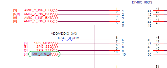
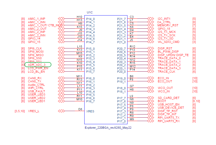
Connection Interface
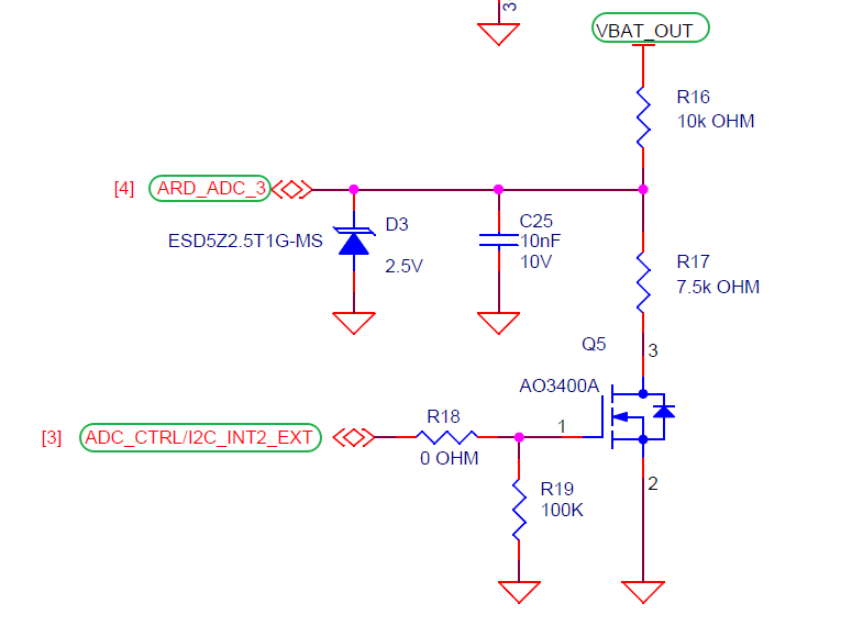
BTB Connector
MCU Pins
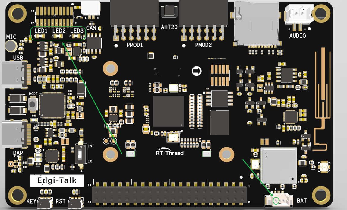
Physical Board Location
Software Description
The project is developed based on the Edgi-Talk platform.
Uses RT-Thread as the operating system kernel.
Example features:
ADC initialization and sampling
LED indicator blinking
ADC sampling results printed via serial port
The project has a clear structure, making it easy for users to understand the ADC driver and RT-Thread threading mechanism.
Usage Instructions
Compilation and Download
Open the project and complete the compilation.
Connect the board’s USB port to the PC using the onboard debugger (DAP).
Use the programming tool to flash the generated firmware onto the board.
Runtime Behavior
After flashing, power on the board to run the example.
The blue indicator LED blinks every 500 ms, indicating normal system operation.
ADC samples battery voltage and prints results to the serial port as shown below:
Value is: 3.123 V
Value is: 3.125 V
...
Notes
To modify the graphical configuration of the project, open the configuration file using the following tool:
tools/device-configurator/device-configurator.exe
libs/TARGET_APP_KIT_PSE84_EVAL_EPC2/config/design.modus
After making changes, save the configuration and regenerate the code.
Boot Sequence
The system boot sequence is as follows:
+------------------+
|   Secure M33     |
|   (Secure Core)  |
+------------------+
          |
          v
+------------------+
|       M33        |
| (Non-Secure Core)|
+------------------+
          |
          v
+-------------------+
|       M55         |
| (Application Core)|
+-------------------+
⚠️ Please strictly follow the boot sequence above when flashing firmware, or the system may fail to start properly.
If the example project does not run correctly, compile and flash the Edgi-Talk_M33_S_Template project first to ensure proper initialization and core startup sequence before running this example.
To enable the M55 core, configure the M33 project as follows:
RT-Thread Settings --> Hardware --> select SOC Multi Core Mode --> Enable CM55 Core