Edgi-Talk_M33_Blink_LED Example Project
中文 | English
Introduction
This example project is based on the Edgi-Talk platform and demonstrates the blue LED blinking function running on the RT-Thread real-time operating system. Through this project, users can quickly verify the board-level GPIO configuration and LED control logic, providing a fundamental reference for future hardware control and application development.
GPIO Overview
GPIO (General Purpose Input/Output) is one of the most commonly used peripheral interfaces in MCUs. It can be configured in software as either input mode or output mode:
Input mode: Used to read external voltage levels, such as button input.
Output mode: Used to control peripheral signals, such as lighting an LED or driving a buzzer.
RT-Thread GPIO Abstraction
RT-Thread provides a PIN device driver framework, which abstracts hardware differences through a unified API interface:
rt_pin_mode(pin, mode): Set the pin mode (input/output/pull-up/pull-down, etc.)rt_pin_write(pin, value): Output a voltage level (high/low)rt_pin_read(pin): Read the input voltage level
This allows developers to perform GPIO control without directly manipulating registers, using RT-Thread’s API instead.
In this example, the LED pin is configured as output mode, and software toggles the output level in a loop to make the LED blink.
Software Description
The project is developed based on the Edgi-Talk platform.
Example functionalities include:
Blue LED blinking periodically
GPIO output control
The project structure is simple and easy to understand, helping users grasp LED control logic and hardware driver interfaces.
Hardware Description
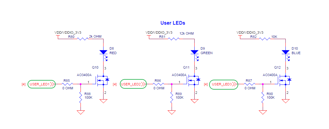
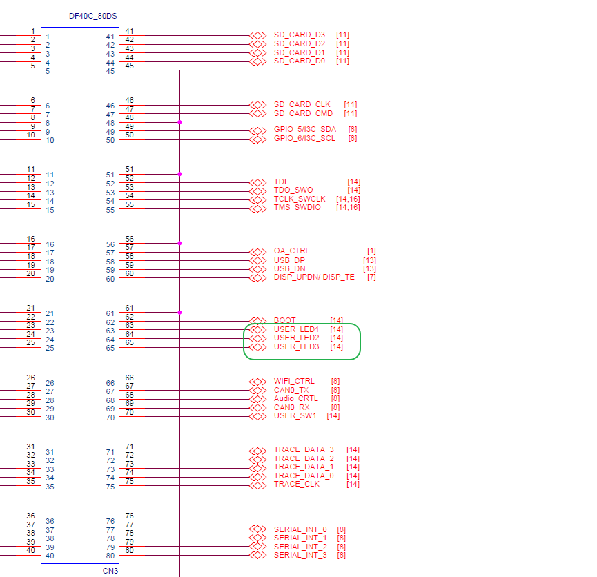
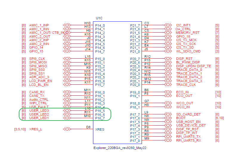
As shown above, the Edgi-Talk board provides three user LEDs: USER_LED1 (RED), USER_LED2 (GREEN), and USER_LED3 (BLUE). USER_LED2 corresponds to pin P16_6. When the MCU outputs a high level, the LED turns on; when the MCU outputs a low level, the LED turns off.
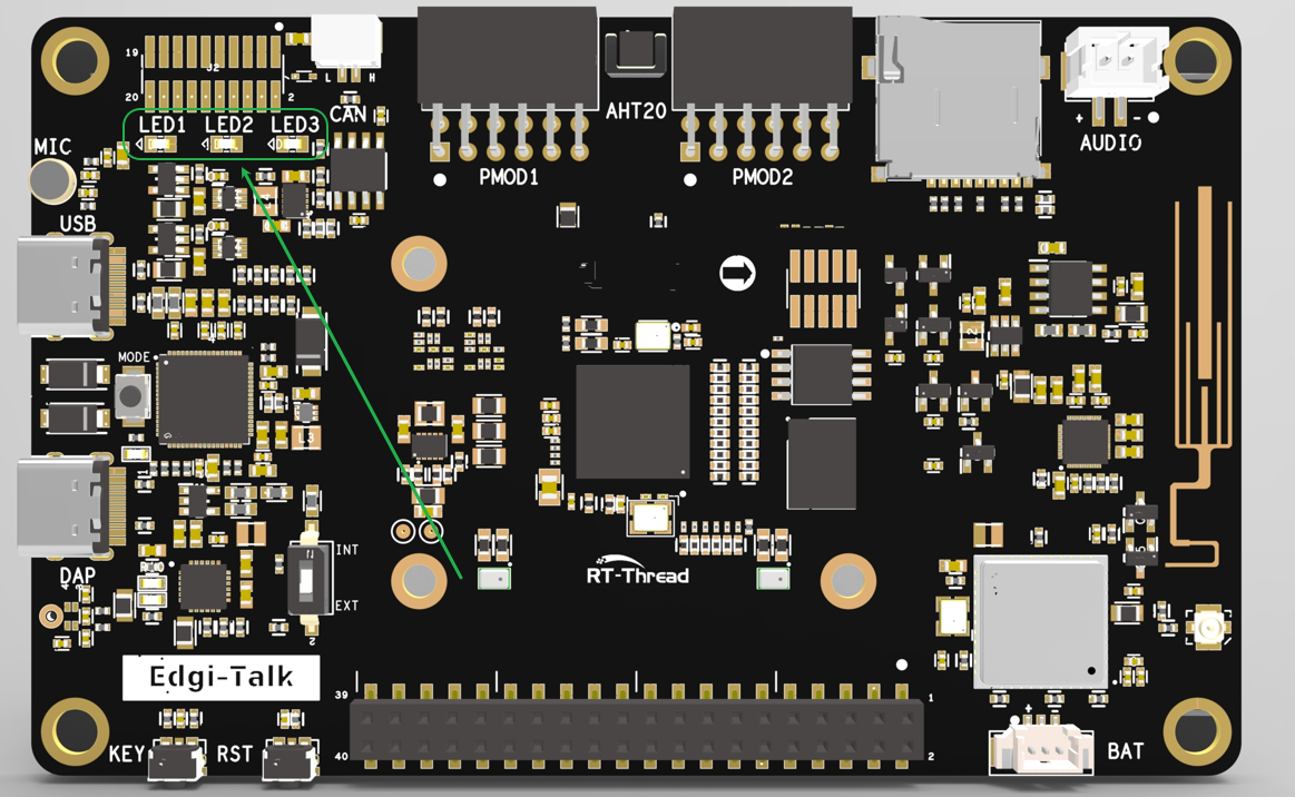
The LED location on the board is shown below:
Usage Instructions
Compilation and Download
Open the project and complete the compilation.
Connect the board’s USB port to the PC using the onboard debugger (DAP).
Use the programming tool to flash the generated firmware to the development board.
Runtime Behavior
After flashing, power on the board to run the example project.
The blue LED blinks every 500 ms, indicating normal GPIO operation and system scheduling.
Users can modify the blinking interval or LED control logic as needed.
Notes
To modify the graphical configuration of the project, open the configuration file using the following tool:
tools/device-configurator/device-configurator.exe
libs/TARGET_APP_KIT_PSE84_EVAL_EPC2/config/design.modus
After modification, save the configuration and regenerate the code.
Boot Sequence
The system boot sequence is as follows:
+------------------+
|   Secure M33     |
|   (Secure Core)  |
+------------------+
          |
          v
+------------------+
|       M33        |
| (Non-Secure Core)|
+------------------+
          |
          v
+-------------------+
|       M55         |
| (Application Core)|
+-------------------+
⚠️ Please strictly follow the boot sequence above when flashing firmware; otherwise, the system may not run properly.
If the example project does not run correctly, compile and flash the Edgi-Talk_M33_S_Template project first to ensure proper initialization and core startup before running this example.
To enable the M55 core, configure the M33 project as follows:
RT-Thread Settings --> Hardware --> select SOC Multi Core Mode --> Enable CM55 Core