Edgi_Talk_M33_IPC Dual-Core Communication Example Project
中文 | English
Overview
This project implements IPC (Inter-Processor Communication) dual-core communication on the Edgi-Talk M33 core, demonstrating message passing between Cortex-M33 and Cortex-M55.
M33 acts as the sender, periodically sending “Hello M33” messages to M55 and receiving “Hello M55” replies.
Default Configuration
Communication frequency: 1000ms
Message format: ASCII encoded text messages
Uses Infineon PSoC E84 on-chip IPC Pipe hardware
Build and Flash
Build the project using RT-Thread Studio or SCons.
Flash firmware to M33 core via KitProg3 (DAP).
Both M33 and M55 projects must be built and flashed for dual-core communication.
Connect serial port to view communication logs as shown below:
Important Notes
Serial Connection
This project uses UART5 as the debug serial port. An external CH340 USB-to-Serial module is required:
Serial Port: UART5
Baud Rate: 115200
Data Bits: 8
Stop Bits: 1
Parity: None
CH340 Module Connection
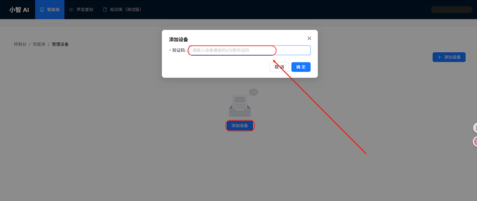
Connect the CH340 module to the development board as follows:
Connection Diagram:
⚠️ Important Notes:
TX and RX must be cross-connected (CH340 TX to board RX)
Ensure GND is common between both devices
To run an M55 project, it is recommended to flash Edgi_Talk_M33_Template first. It is a clean M33 project and is suitable as the base firmware before starting M55.
Usage
1. Configuration and Build
Open in RT-Thread Studio:
RT-Thread Settings -> Hardware Drivers Config -> On-chip Peripheral Drivers
Check Enable IPC option.
2. Run Example
Step 1: Start M55 Receiver
In M55 serial terminal, type:
msh> ipc_test_run
M55 will enter listening mode, waiting for messages from M33.
Step 2: Start M33 Sender
In M33 serial terminal, type:
msh> ipc_test_run
M33 will start sending “Hello M33” messages every second and receive “Hello M55” replies.
3. Observe Output
M33 Output Example:
========================================
[M33] IPC Demo Started
----------------------------------------
Mode:     Sender
Target:   Cortex-M55
Message:  Hello M33
Interval: 1000 ms
========================================

[M33] TX -> [M55]: "Hello M33" | Seq:     1 | Time:     1234 ms
[M33] RX <- [M55]: "Hello M55" | Seq:     1 | Time:     1256 ms
[M33] TX -> [M55]: "Hello M33" | Seq:     2 | Time:     2234 ms
[M33] RX <- [M55]: "Hello M55" | Seq:     2 | Time:     2256 ms
----------------------------------------
[M33] Statistics: TX=10, RX=10
----------------------------------------
M55 Output Example:
========================================
[M55] IPC Listener Running
----------------------------------------
Mode:     Receiver & Responder
Peer:     Cortex-M33
Response: Hello M55
========================================

[M55] RX <- [M33]: "Hello M33" | Seq:     1 | Time:     1250 ms
[M55] TX -> [M33]: "Hello M55" | Seq:     1 | Time:     1252 ms
[M55] RX <- [M33]: "Hello M33" | Seq:     2 | Time:     2250 ms
[M55] TX -> [M33]: "Hello M55" | Seq:     2 | Time:     2252 ms
----------------------------------------
[M55] Statistics: RX=10, TX=10
----------------------------------------
Data Protocol
IPC communication uses the edge_rc_frame_t structure:
typedef struct {
    uint8_t client_id;          // Client ID
    uint16_t intr_mask;         // Interrupt mask
    uint8_t role;               // Role identifier (M33/M55_ECHO)
    uint32_t magic;             // Magic word (0x5243444DU)
    uint32_t seq;               // Sequence number
    uint16_t channel[8];        // 8-channel data (stores ASCII messages)
    uint32_t checksum;          // Checksum
} edge_rc_frame_t;
Message “Hello M33” encoding:
channel[0] = 0x4865  /* 'He' */
channel[1] = 0x6C6C  /* 'll' */
channel[2] = 0x6F20  /* 'o '  (space) */
channel[3] = 0x4D33  /* 'M3' */
channel[4] = 0x0033  /* '3' */
Startup Sequence
M55 depends on M33 boot flow. Flash in this order:
+------------------+
|   Secure M33     |
|  (Secure Core)   |
+------------------+
		  |
		  v
+------------------+
|       M33        |
|   (IPC Sender)   |
+------------------+
		  |
		  v
+-------------------+
|       M55         |
|  (IPC Receiver)   |
+-------------------+
Hardware Connection
This example uses Infineon PSoC E84 on-chip IPC hardware:
Uses IPC Pipe hardware in CM0P
CM33 uses EP1 (Endpoint 1)
CM55 uses EP2 (Endpoint 2)
Uses semaphores for mutual exclusion
No external wiring required
Configuration Parameters
The following parameters can be modified in libraries/HAL_Drivers/ipc_common.h:
EDGE_IPC_FRAME_POOL_SIZE: Transmit buffer pool size (default 64)EDGE_IPC_RX_QUEUE_SIZE: Receive queue size (default 128)EDGE_IPC_SEMA_RETRY_MAX: Semaphore retry count (default 2)
Notes
⚠️ Note: This project requires RT-Thread Studio 2.2.9 or higher.
This project targets M33 core as IPC sender.
For M55 receiver, see projects/Edgi_Talk_IPC/Edgi_Talk_M55_IPC/README.md.
IPC driver is located at
libraries/HAL_Drivers/drv_ipc.c.Ensure both cores are configured with
BSP_USING_IPC.
References
IPC driver referenced from
D:\Desktop\Fmt\FMT-Firmware\target\infineon\edge-e83Infineon PSoC E84 Technical Reference Manual