Modbus-TCP/IP Usage Instructions
English | 中文
Introduction
This example is based on the agile_modbus package and demonstrates Modbus protocol communication over TCP/IP.
Hardware Requirements
FSP Configuration Instructions
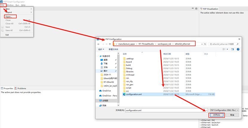
Open the project configuration file
configuration.xml:
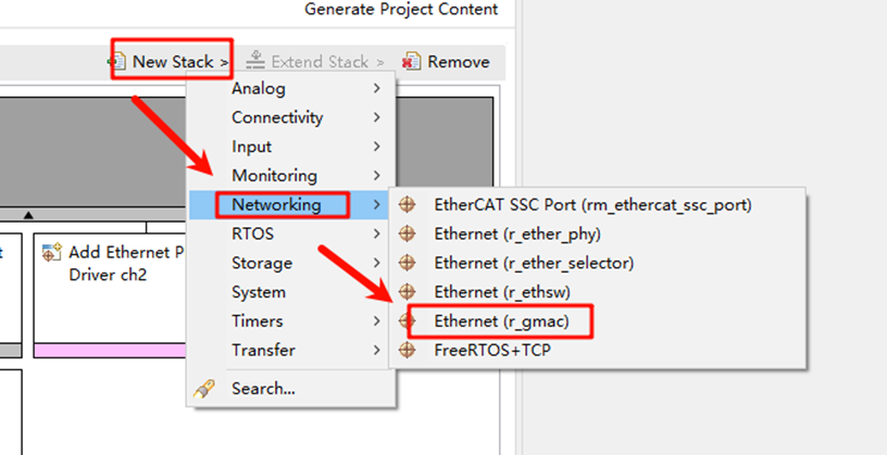
Add the
r_gamcstack:
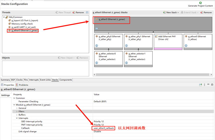
Click on
g_ether0Ethernet and configure the interrupt callback function asuser_ether0_callback:
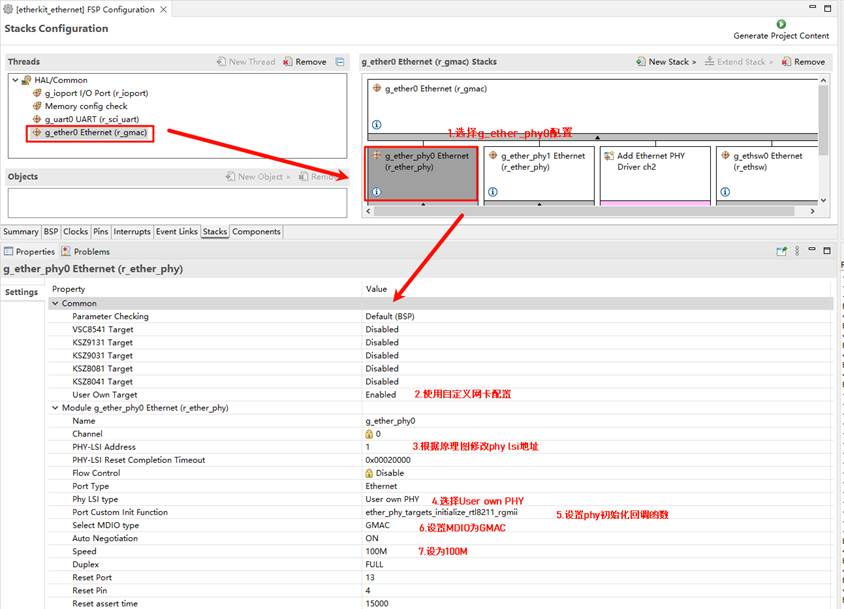
Next, configure the PHY information. Select
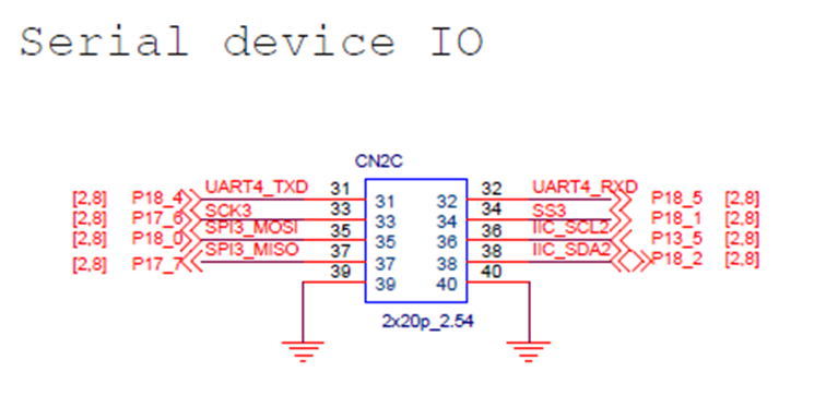
g_ether_phy0, set the Common configuration to “User Own Target,” change the PHY LSI address to 1 (refer to the schematic for the exact address), and set the PHY initialization callback function toether_phy_targets_initialize_rtl8211_rgmii(). Also, set MDIO to GMAC.
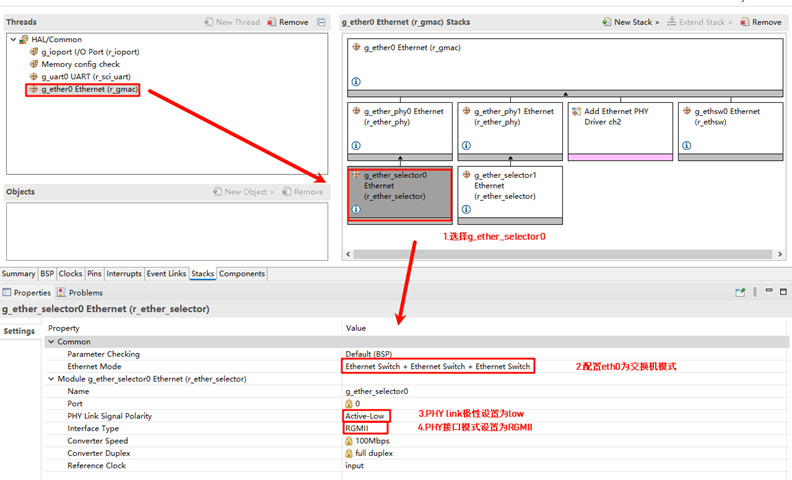
Configure
g_ether_selector0, set the Ethernet mode to Switch mode, set the PHY link to default active-low, and configure the PHY interface mode to RGMII.
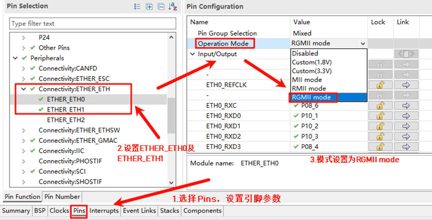
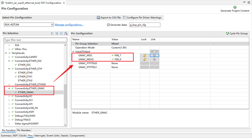
Configure the network card pin parameters, setting the operation mode to RGMII:
ETHER_GMAC configuration:
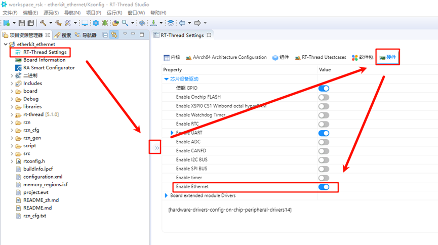
RT-Thread Settings Configuration
Return to the Studio project, configure RT-Thread Settings, select hardware options, and enable Ethernet by finding the chip device driver:
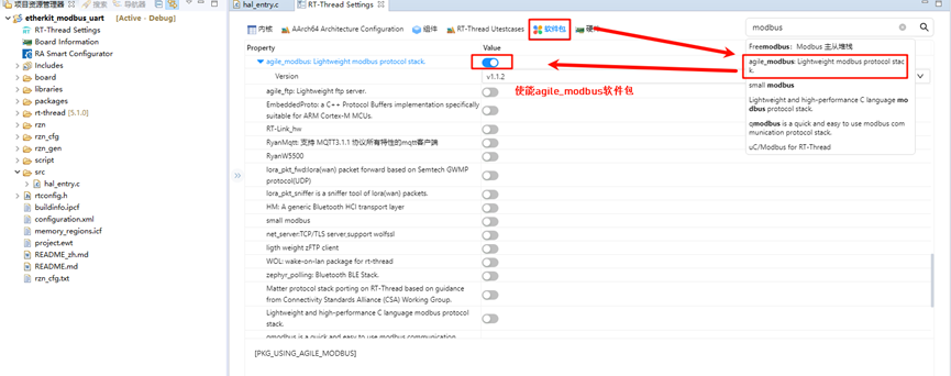
In the software package interface, search for “modbus,” select the agile_modbus package, and enable it:
Compilation & Download
RT-Thread Studio: Download the EtherKit resource package in the RT-Thread Studio package manager, create a new project, and compile it.
IAR: First, double-click
mklinks.batto create the link between the rt-thread and libraries folders. Then, use Env to generate the IAR project. Finally, double-clickproject.ewwto open the IAR project and compile it.
Once the compilation is complete, connect the Jlink interface of the development board to the PC and download the firmware to the board.
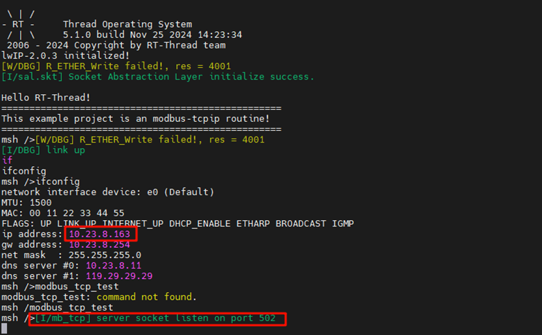
Running Results
First, use an Ethernet cable to connect the development board’s network port to a switch (if your computer has an extra Ethernet port, you can also use a shared adapter). Then, enter the command modbus_tcp_test in the serial tool to start the Modbus-TCP example:
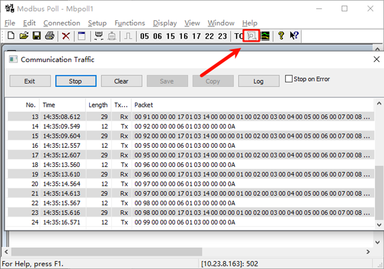
Open the Modbus Poll software, connect to the development board, set the mode to Modbus TCP/IP, set the IP to the development board’s IP address, and the port number to 502:

After a successful connection, the development board’s terminal will display that the Modbus client is connected:
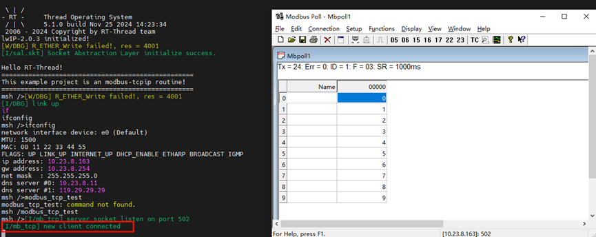
Return to the Modbus Poll software, and you will see that the read and write coil functions are working correctly: