SCI_SPI Driver Usage Instructions
English | 中文
Introduction
This example demonstrates how to use the RT-Thread SCI_SPI framework on the EtherKit.
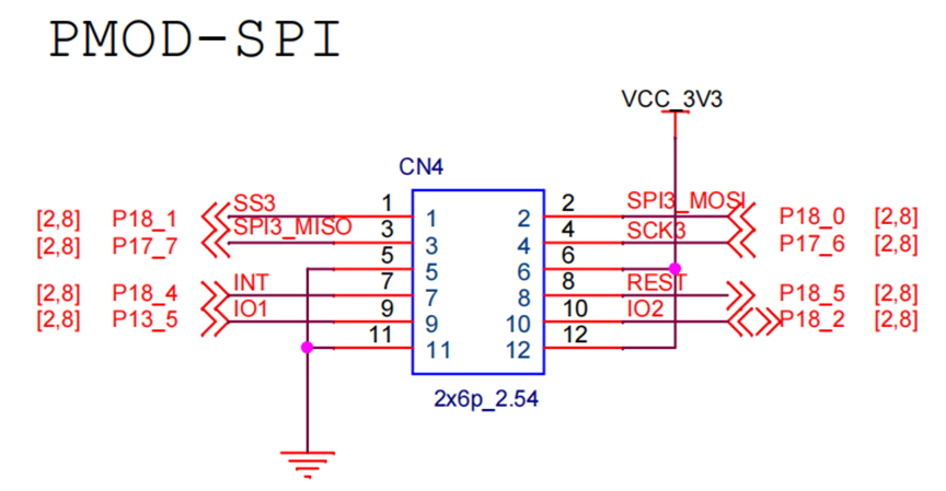
Hardware Description
The EtherKit board has a PMOD interface, which is connected to the SCI_SPI3 of the R9A07G084M08GBG chip.
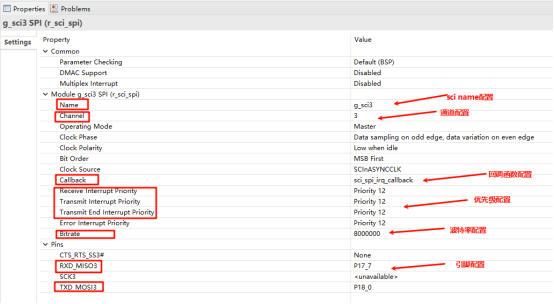
FSP Configuration Instructions
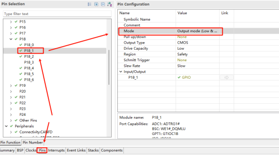
Open the FSP tool, create a new stack, and select r_sci_spi3:
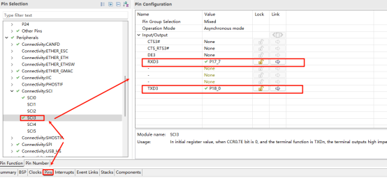
RT-Thread Settings Configuration
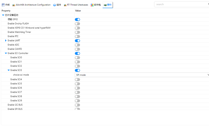
In RT-Thread Settings, enable SCI hardware and configure SCI3 mode as SPI:
Example Project Description
This example uses the RT-Thread SCI driver framework to perform a loopback test on the PMOD interface (connecting PMOD’s SPI3_MOSI to SPI3_MISO). The code is as follows:
void spi_loop_test(void)
{
#define TEXT_NUMBER_SIZE 1024
#define SPI_BUS_NAME "sci3s"
#define SPI_NAME "spi30"
    static uint8_t sendbuf[TEXT_NUMBER_SIZE] = {0};
    static uint8_t readbuf[TEXT_NUMBER_SIZE] = {0};
    for (int i = 0; i < sizeof(readbuf); i++)
    {
        sendbuf[i] = i;
    }
    static struct rt_spi_device *spi_dev = RT_NULL;
    struct rt_spi_configuration cfg;
    rt_hw_sci_spi_device_attach(SPI_BUS_NAME, SPI_NAME, NULL);
    cfg.data_width = 8;
    cfg.mode = RT_SPI_MASTER | RT_SPI_MODE_0 | RT_SPI_MSB | RT_SPI_NO_CS;
    cfg.max_hz = 1 * 1000 * 1000;
    spi_dev = (struct rt_spi_device *)rt_device_find(SPI_NAME);
    if (RT_NULL == spi_dev)
    {
        rt_kprintf("spi sample run failed! can't find %s device!\n", SPI_NAME);
        return;
    }
    rt_spi_configure(spi_dev, &cfg);
    rt_kprintf("%s send:\n", SPI_NAME);
    for (int i = 0; i < sizeof(sendbuf); i++)
    {
        rt_kprintf("%02x ", sendbuf[i]);
    }
    rt_spi_transfer(spi_dev, sendbuf, readbuf, sizeof(sendbuf));
    rt_kprintf("\n\n%s rcv:\n", SPI_NAME);
    for (int i = 0; i < sizeof(readbuf); i++)
    {
        if (readbuf[i] != sendbuf[i])
        {
            rt_kprintf("SPI test fail!!!\n");
            break;
        }
        else
            rt_kprintf("%02x ", readbuf[i]);
    }
    rt_kprintf("\n\n");
    rt_kprintf("SPI test end\n");
}
Compilation & Download
RT-Thread Studio: In RT-Thread Studio’s package manager, download the EtherKit resource package, create a new project, and compile it.
IAR: First, double-click
mklinks.batto create symbolic links between RT-Thread and the libraries folder. Then, use theEnvtool to generate the IAR project. Finally, double-clickproject.ewwto open the IAR project and compile it.
After compilation, connect the development board’s JLink interface to the PC and download the firmware to the development board.
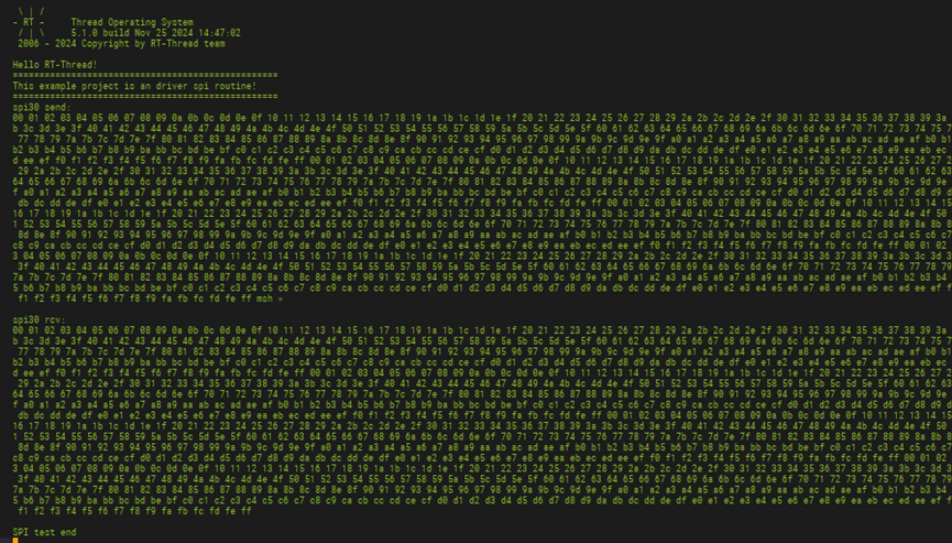
Run Effect
When using a serial tool, you can observe that the data sent and received in the SPI loopback test matches: