USB-PCDC Driver Usage Instructions
English | 中文
Introduction
This example demonstrates how to implement a virtual serial port over USB. USB PCDC (USB Communication Device Class) is a subclass of the USB communication device class (CDC) that is commonly used to implement virtual serial communication functionality. In embedded device development, USB PCDC is often used to simulate a serial communication port (such as a COM port) over a USB interface, allowing data interaction with a host.
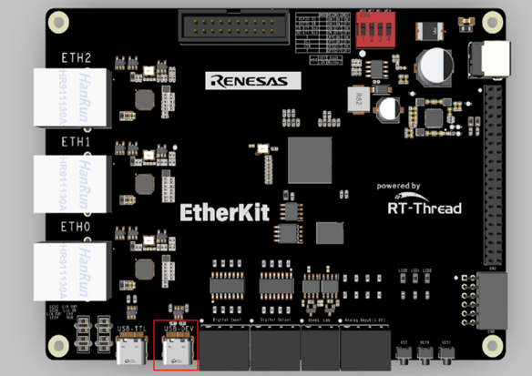
Hardware Requirements
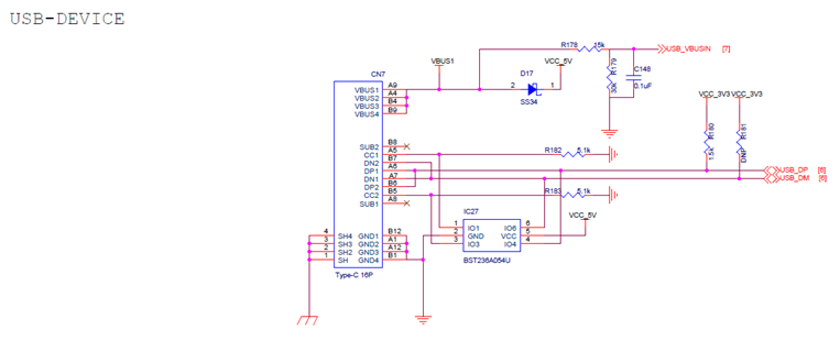
EtherKit provides a USB-Device peripheral, located on the development board as shown below:
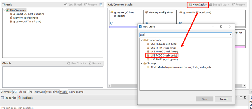
FSP Configuration Instructions
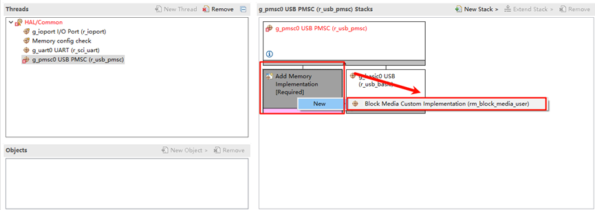
Open the project’s
configuration.xmlfile using FSP and add theusb_pmcsstack:
Add
g_rm_block_media0:
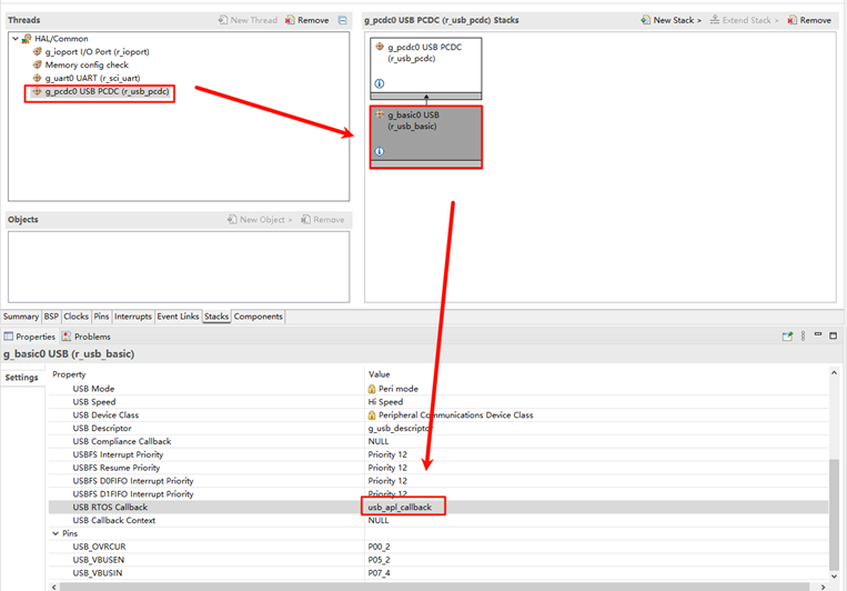
Select
g_basic0_usband set the interrupt callback function tousb_apl_callback:
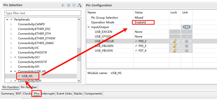
Next, configure the USB pins. Find
USB_HSand enable it:
Build Configuration
Locate the file at the specified path in the project: .\rzn\SConscript, and replace its content with the following:
Import('RTT_ROOT')
Import('rtconfig')
from building import *
from gcc import *

cwd = GetCurrentDir()
src = []
group = []
CPPPATH = []

if rtconfig.PLATFORM in ['iccarm'] + GetGCCLikePLATFORM():
    if rtconfig.PLATFORM == 'iccarm' or GetOption('target') != 'mdk5':
        src += Glob('./fsp/src/bsp/mcu/all/*.c')
        src += Glob('./fsp/src/bsp/mcu/all/cr/*.c')
        src += Glob('./fsp/src/bsp/mcu/r*/*.c')
        src += Glob('./fsp/src/bsp/cmsis/Device/RENESAS/Source/*.c')
        src += Glob('./fsp/src/bsp/cmsis/Device/RENESAS/Source/cr/*.c')
        src += Glob('./fsp/src/r_*/*.c')
        src += Glob('./fsp/src/r_usb_basic/src/driver/*.c')
        src += Glob('./fsp/src/r_usb_basic/src/hw/*.c')
        src += Glob('./fsp/src/r_usb_pcdc/src/*.c')
        CPPPATH = [ cwd + '/arm/CMSIS_5/CMSIS/Core_R/Include',
                    cwd + '/fsp/inc',
                    cwd + '/fsp/src/inc',
                    cwd + '/fsp/inc/api',
                    cwd + '/fsp/inc/instances',
                    cwd + '/fsp/src/r_usb_basic/src/driver/inc',
                    cwd + '/fsp/src/r_usb_basic/src/hw/inc',
                    cwd + '/fsp/src/r_usb_pcdc/src/inc',]

group = DefineGroup('rzn', src, depend = [''], CPPPATH = CPPPATH)
Return('group')
If you are using Studio for development, right-click on the project and select Sync SCons Configuration to Project.
For IAR development, right-click within the current project to open the environment, and run the following command to regenerate the configuration:
scons --target=iar
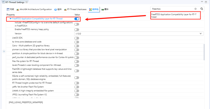
RT-Thread Settings Configuration
The USB example currently uses the FreeRTOS interface driver, so we also need to enable the FreeRTOS compatibility layer package:
Compilation & Download
RT-Thread Studio: Download the EtherKit resource package in the RT-Thread Studio package manager, create a new project, and compile it.
IAR: First, double-click
mklinks.batto create the link between the rt-thread and libraries folders. Then, use Env to generate the IAR project. Finally, double-clickproject.ewwto open the IAR project and compile it.
Once the compilation is complete, connect the Jlink interface of the development board to the PC and download the firmware to the board.
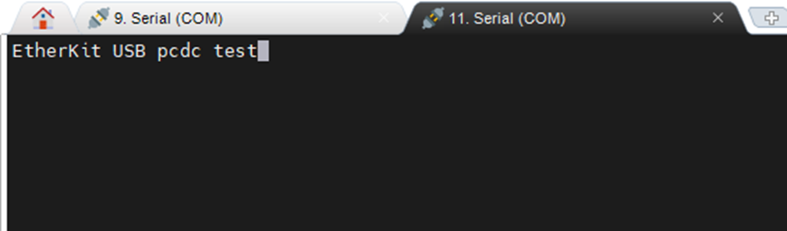
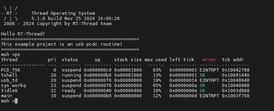
Running Results
After generating the FSP configuration, compile and download the firmware to the development board. The example will automatically start, and you will see an additional USB device in the file manager:
Next, open the virtual serial port device and test character input: