Gino_factory
1. Introduction
This project combines LVGL, camera, MQTT, Ethernet, storage, and common peripherals on the GD32H77D Gino board. Use the touch interface and console to operate the enabled features.
Primary device: lcd.
All examples keep uart1 as the FinSH/MSH console at 115200-8-N-1, and PC4 LED is used as the run indicator.
Current project provides the following MSH commands:
Command |
Function |
Example/Note |
|---|---|---|
|
Request live camera preview on the LCD. |
Use after the display and camera are ready. |
|
Start the GD32VW553 MQTT demo. |
Connects Wi-Fi, Broker, and subscription path. |
|
Check the connection state and IP address of the netdev. |
Confirm that the network is ready. |
|
List registered system devices. |
Confirm that UART, PIN, buses, and target devices exist. |
|
Scan external I2C addresses |
Provided by |
The I2C touch page scans only the external hwi2c1 bus (SCL PH4, SDA PB11). Its Scan button uses address-only transfers in board_demo_backend.c. The camera and GT911 touch controller use hwi2c2 and hwi2c3 respectively; these buses have no scan entry in the UI. The console uses the bundled i2c-tools v1.0.0 package in hardware bus mode. Run mklinks.bat on Windows or sh mklinks.sh on Linux before opening the project. Run i2c for scan/read/write usage; scan ranges are hexadecimal with an exclusive stop address.
The SPI page performs a full-duplex SPI3 loopback test: connect PF1 (MOSI) to PF0 (MISO); SCK is PE12. The test uses mode 0, 8-bit data and no chip select. Select the maximum clock frequency and transfer length, then press Run loopback. The screen log shows queuing, configuration, the complete TX/RX hex data and PASS/FAIL, including the first mismatching byte offset and values.
The I2C page uses a 16-column address matrix like i2c-tools: responding devices show their address, -- means no response, .. means unscanned, and !! marks a probe error. Reserved addresses remain blank. The scan covers 0x08-0x77, updates each address result, and reports the device count and elapsed time. There is no per-address sleep. Bus locking waits at most 100 ms; while holding the lock, each probe temporarily caps the driver’s wait-stage timeout at 20 ms and then restores it. Timeouts or other bus errors stop the scan and preserve partial results instead of reporting an incomplete scan as an empty bus.
The Scan log retains responding addresses, errors and the final result. SPI and I2C tests disable their buttons and parameter selectors while pending or running, and report submission errors. Logs also go to the console; each test retains the latest 3 KB for the current request in a scrollable screen panel. These screen logs cover requests made from the touch UI. The I2C page scans addresses only; it does not program chip data or firmware.
1.1 Wi-Fi Configuration
Before running the factory demo, configure the Wi-Fi SSID and password for your own network. The procedure and screenshots follow Gino_component_mqtt, but each project has its own configuration: make these changes in Gino_factory.
The onboard GD32VW553 AT module uses UART4 (TX PB12, RX PB13, AF14), with PC5 controlling reset. Its network device is wifi0; UART1 remains the console.
Env
In Env, enter
projects\Gino_factoryfrom the SDK root and runmklinks.batif the shared directory links have not been created.Run
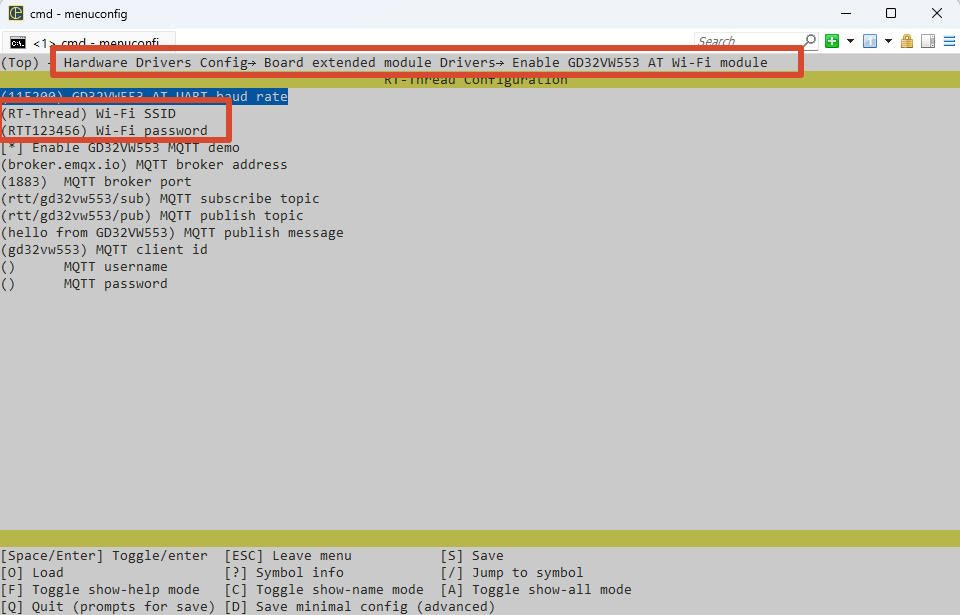
menuconfigand open the following menu:Hardware Drivers Config -> Board extended module Drivers -> Enable GD32VW553 AT Wi-Fi moduleKeep the module enabled and set
Wi-Fi SSIDandWi-Fi passwordto your network’s values. KeepGD32VW553 AT UART baud rateat115200unless the module firmware uses a different rate.Save and exit, then run
scons --pyconfig-silentto updatertconfig.h. For MDK5, also runscons --target=mdk5to update the project files.
RT-Thread Studio
Open the factory project’s
RT-Thread Settingsand select the hardware tab.Expand
Board extended module Drivers -> Enable GD32VW553 AT Wi-Fi moduleand keep the module enabled.Set
Wi-Fi SSIDandWi-Fi password, confirm the AT UART baud rate, and save the settings to update the project configuration.
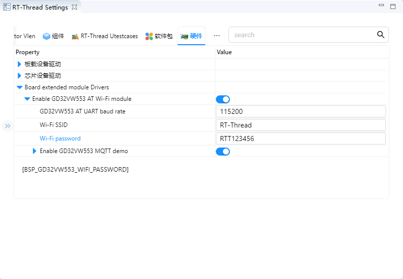
The two fields correspond to BSP_GD32VW553_WIFI_SSID and BSP_GD32VW553_WIFI_PASSWORD. Use your own network values instead of the values shown in the screenshots. After saving, rebuild and download the factory firmware, then reset the board to apply the configuration.
1.2 Wi-Fi and MQTT Verification
Run ifconfig on UART1 and confirm that wifi0 is up, its link is up, and its IP address is not 0.0.0.0. The factory project also enables Ethernet e0; an Ethernet connection alone does not confirm that Wi-Fi is ready. If wifi0 does not connect, check the SSID, password, access point availability, module power/reset, and AT UART baud rate.
To use MQTT, keep Enable GD32VW553 MQTT demo enabled in the same configuration menu and set the broker address/port, subscribe/publish topics, client ID, and optional username/password for your service. You can use your own topics. Use a numeric IPv4 broker address when the module firmware does not support DNS through AT+CIPDOMAIN.
After applying the configuration and confirming that wifi0 is ready, run:
gd32vw553_mqtt_start
gd32vw553_mqtt_pub rtt/gino hello
gd32vw553_mqtt_stop
Wait for the MQTT connection and subscription to succeed before publishing. Replace rtt/gino with your own topic and confirm that the broker/subscriber receives the message. The MQTT demo temporarily selects wifi0 as the default network device and restores the previous default when it stops.
2. Concurrent Peripheral System Integration Details
The factory project verifies that independently working features can share pins, initialization levels, DMA, cache, SDRAM, default routes, and heap. Display continuously scans SDRAM, camera and ENET use DMA, Wi-Fi/MQTT selects wifi0 through SAL, and filesystems mount after devices register. This more closely represents a real product workload.
The complete data path is:
driver registration -> DFS/lwIP/LVGL/SAL -> concurrent display + camera + storage + e0/wifi0 + MQTT
The protocol layer only defines communication and data processing rules. Final validation still depends on controller clocks, pin multiplexing, interrupt/DMA handling, and upper-layer state machines. Device discovery, bus registration, or a successful build cannot replace a complete data transfer test.
3. GD32H77D Multiple Buses, DMA Engines, and Memories Features
The integrated project uses SDRAM/TLI/DSI, DCI/DMA, ENET1, OSPI0, SDIO1, USBHS, CAN, SPI, I2C, UART, and timers together. It validates shared pins, DMA, cache, bandwidth, memory regions, and interrupt priorities.
4. RT-Thread Integrated Devices and Components Device Interface
RT-Thread runs the device framework, DFS/FAL/FatFs, lwIP/netdev/SAL, at_device, LVGL, touch, camera, and MQTT threads together. Stable names, init levels, and IPC coordinate modules.
Primary device: lcd. Use list_device and gino_device_probe first to check whether the device has been registered. Upper-layer file system, network, or GUI components still need separate validation for mount, link, or refresh state.
5. Hardware
Enables the 720 x 720 LCD, GT911, OV7670, GD32VW553, ENET1, OSPI flash, SDIO, USB, CAN, SPI, I2C, and PWM. Follow each standalone project’s wiring and electrical requirements.
Default console: UART1, PA2/PA3, AF7, 115200-8-N-1.
6. Example
Source paths below are relative to the project directory in the SDK repository:
applications/board_demo.capplications/board_demo_backend.capplications/lv_port.capplications/ov7670_preview.capplications/gd32vw553_mqtt_demo.cboard/SConscript
tests/run_host_tests.ps1 uses host GCC and a simulated bus to check command dispatch, scan results, timeout aborts and timeout restoration without building firmware. It defaults to MSYS2 UCRT64 GCC; use -Compiler to select another path. Tests extract the current backend functions directly and do not replace board checks of wiring, ACK signals or actual scan timing.
Read applications/main.c and applications/device_probe.c first, then follow the data path into the corresponding driver, component, or package. The example keeps MSH commands so device registration and runtime state can be observed without changing application code.
6.1 Runtime Commands
ov7670_preview startgd32vw553_mqtt_startifconfiglist_devicei2c scan hwi2c1 08 78
6.2 Operation Steps
Check power, wiring, external modules, and interface logic levels.
Reset the development board and confirm that the UART1 console is available and PC4 LED blinks normally.
Run
list_deviceand confirm that dependency buses and target devices are registered.Run the commands above in order while observing return values, external waveforms, network state, or display results.
7. Runtime Results
7.1 Expected Behavior
list_deviceshows enabled display, touch, camera, storage, network, and bus devices.LVGL, preview, Ethernet/Wi-Fi, and filesystems start independently and coexist under reasonable load.
The touch UI provides board feature controls; the console can operate camera, networking, and MQTT.
The I2C touch page and
i2c scanlist responding slave addresses on the selected bus.The SPI loopback page shows TX/RX data and verification results; the I2C page shows scan progress logs and responding addresses.